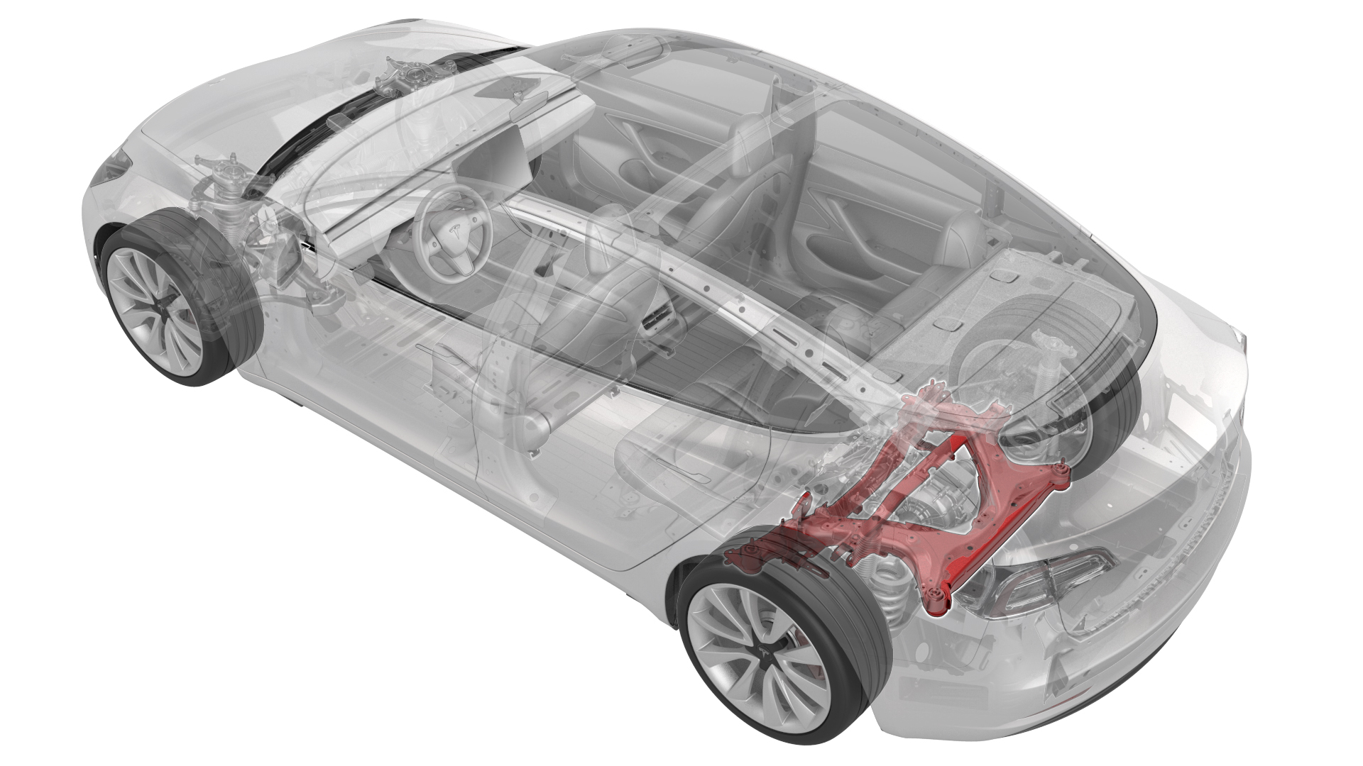
Subframe Assembly - Rear (Remove and Replace)
 Correction code
30010202
4.08
NOTE: Unless otherwise explicitly
stated in the procedure, the above correction code and FRT reflect all of the work
required to perform this procedure, including the linked procedures. Do not stack correction codes unless
explicitly told to do so.
NOTE: See Flat Rate
Times to learn more about FRTs and how they are created.
NOTE: See Personal Protection to make sure wearing proper PPE when
performing the below procedure. NOTE: See Ergonomic Precautions for safe and healthy working
practices.
Correction code
30010202
4.08
NOTE: Unless otherwise explicitly
stated in the procedure, the above correction code and FRT reflect all of the work
required to perform this procedure, including the linked procedures. Do not stack correction codes unless
explicitly told to do so.
NOTE: See Flat Rate
Times to learn more about FRTs and how they are created.
NOTE: See Personal Protection to make sure wearing proper PPE when
performing the below procedure. NOTE: See Ergonomic Precautions for safe and healthy working
practices.
Equipment:
- 1099645-00-B Fixture, Subframe, Model 3
- 1130279-00-A Lifting Sling, Drive Unit, Model 3 (NA, APAC)
- 1130481-00-A Adapter, Subframe, Body Shop, Model 3
- 1096075-00-A Tool, Hub Puller, Hydraulic
- 1498673-00-A KIT, CABLE AXLE REMOVER, MS/MX/M3
- 1140311-00-A Lever Lock, HV Connector, Model 3
Remove
- Remove the rear subframe assembly. See Subframe Assembly - Rear (Remove and Install).
-
Release the clip, disconnect the rear
drive unit inlet hose from the inverter coolant coupling, and then plug the
coupling.
-
Release the clip that attaches the
rear drive unit inlet hose to the HV harness bracket, and then remove the hose from the
rear drive unit.
-
Remove the bolt that attaches the HV
harness bracket to the inverter.
-
Slide the release to unlock the rear
drive unit HV connector handle of the rear drive unit to HV battery harness from the
secured position.
-
Fully raise the handle on the rear
drive unit HV connector.
- Remove the rear drive unit HV connector from the rear drive unit HV header.
- Remove the rear drive unit HV cable from the subframe.
- Release the clip that attaches the rear drive unit ground harness to the rear subframe.
-
Disconnect the electrical harness from
the inverter low voltage connector.
-
Release the clip that attaches the low
voltage electrical harness to the inverter.
-
Disconnect the electrical harness from
the resolver connector.
-
Disconnect the electrical harness from
the oil pump connector.
- Attach the drive unit sling special tool to the rear drive unit.
- Position the drive unit sling tool special tool underneath the gantry, and then attach the special tool to the gantry.
- Raise the drive unit sling tool so that there is a slight tension on the cables.
-
Remove the bolt and nut that attach
the LH mount of the rear drive unit to the subframe.
-
Remove the bolt and nut that attach
the RH bushing of the rear drive unit to the subframe.
-
Remove the bolt that attaches the rear
bushing of the rear drive unit to the subframe.
-
Position the axle remover cable around
the inner joint of the LH rear drive unit halfshaft, and then use a cable tie to hold
the axle remover cable in position.
Figure 1. Axle removed from drive unit for demonstration purposes - Hook the axle remover slide hammer on the 2 axle remover cable loops, and then use the slide hammer to remove the halfshaft from the drive unit.
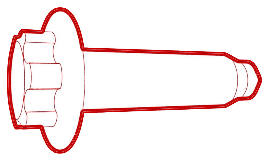
- Install a halfshaft plug into the opening of the gearbox.
- Repeat step 20 through step 22 on the RH side of the rear subframe.
- Raise the drive unit sling tool to lift the rear drive unit out of the rear subframe.
- Lower the rear drive unit onto a protected surface.
- Move the subframe and lifting tool from underneath the drive unit.
-
With assistance, place a ½ Ton economy
transmission jack under the LH suspension assembly.
NoteAvoid the suspension assembly falling.
-
Remove the bolt and nut that attach
the LH lower fore link to the rear subframe.
-
With an assistant, remove the bolt and
nut that attach the LH upper fore link to the rear subframe.
-
Remove the nut and bolt that attach
the LH toe link to the rear subframe.
-
Remove the nut and bolt that attach
the LH lower control arm to the rear subframe.
-
Remove the nut and bolt that attach
the LH upper aft link to the rear subframe.
-
Release the clip that attaches the LH
rear ABS wheel speed sensor connector to the subframe, and then disconnect the subframe
harness from the connector.
TIpUse a mechanical pickup tool to hold the connector in place, and then release the connector clip with a screwdriver.
-
Release the clip that attaches the
rear LH ABS wheel speed sensor cable to the rear subframe bracket.
-
With assistance, remove the LH rear
suspension assembly from the vehicle.
- Repeat step 27 through step 35for the RH side of the rear subframe.
-
Release the clips that attach the
subframe electrical harness to the bottom and top of the rear subframe, and then remove
the electrical harness from the rear subframe.
Figure 2. Top view of the rear subframe Figure 3. Bottom view of the rear subframe -
With an assistant, release the straps,
and then remove the rear subframe from the subframe lifting tool.
Install
- With an assistant, install the new rear subframe onto the subframe lifting tool, and then attach the straps.
-
Install the clips that attach the
electrical harness to the rear subframe.
Figure 4. Top view of the rear subframe Figure 5. Bottom view of the rear subframe -
With assistance, position the LH
suspension assembly onto the rear subframe assembly.
-
With an assistant, install and
hand-tighten the nut and bolt that attach the LH upper aft link to the rear
subframe.
-
With an assistant, install and
hand-tighten the bolt and nut that attach the LH lower aft link to the knuckle.
-
With an assistant, install and
hand-tighten the nut and bolt that attach the LH toe link to the rear subframe.
-
With an assistant, install and
hand-tighten the bolt and nut that attach the LH upper fore link to the rear
subframe.
-
With an assistant, install and
hand-tighten the bolt and nut that attach the LH lower fore link to the rear
subframe.
- Remove the ½ Ton economy transmission jack from under the LH suspension assembly.
-
Install the grommet and fasten the
clip that attach the rear LH ABS wheel speed sensor cable to the rear LH knuckle and
subframe bracket.
-
Connect the subframe electrical
harness to the LH rear ABS wheel speed sensor connector, and then fasten the clip that
attaches the sensor connector to the subframe.
- Repeat step 3 through step 11 for the RH side of the rear subframe.
- With an assistant, position the rear drive unit above the rear subframe, and then lower the drive unit sling tool to install the rear drive unit into the rear subframe.
-
With an assistant, remove the
halfshaft plug from the gearbox, and then install the LH halfshaft to the rear drive
unit. Repeat this step on the RH halfshaft.
CAUTIONWhen installing the halfshaft to the drive unit:
- Take care not to damage or displace the oil seals.
- Make sure that the opening of the snap rings are facing towards the bottom of the drive unit.
- Carefully push the halfshaft into the drive unit until there is an audible "click" from the halfshaft stub contacting the pinion shaft.
- There will be a slight pulling sensation on the halfshaft as the halfshaft circlip locks into place.
- Pull on the inner halfshaft cup to confirm that the circlip is locked into place. If the halfshaft detaches from the drive unit then reinstall the halfshaft and then test that it is fully seated.
- Set the LH halfshaft temporarily on the lower aft link.
-
Install and hand-tighten the bolt that
attaches the rear bushing of the rear drive unit to the subframe.
-
Install and hand-tighten the bolt and
nut that attach the RH bushing of the rear drive unit to the subframe.
-
Install and hand-tighten the bolt and
nut that attach the LH mount of the rear drive unit to the subframe.
- Lower the drive unit sling tool to release the tension on the cables.
- Remove the drive unit sling tool from the gantry.
- Remove the drive unit sling tool from the rear drive unit.
-
Tighten the bolts and nuts that attach
the rear bushing, RH bushing, and LH mount of the rear drive unit to the rear
subframe.
 80 Nm (59.0 lbs-ft)
 - Fasten the clip that attaches the rear drive unit ground harness to the rear subframe.
-
Connect the electrical harness to the
resolver connector.
-
Connect the electrical harness to the
oil pump connector.
-
Fasten the clip that attaches the rear
drive unit inlet hose to the HV harness bracket.
-
Connect the electrical harness to the
inverter low voltage connector.
-
Fasten the clip that attaches the low
voltage electrical harness to the inverter.
- Position the rear drive unit HV cable on the rear subframe.
-
Fully raise the handle on the rear
drive unit HV connector of the rear drive unit to HV battery harness.
-
Install the HV connector special tool
onto the rear drive unit HV connector.
-
Use both hands to firmly connect the
rear drive unit HV connector of the rear drive unit to HV battery harness to the rear
drive unit HV header.
CAUTIONMake sure that the connector fits the header squarely and tightly, and that both retention pins enter the handle.
- Remove the HV connector special tool from the rear drive unit HV connector.
-
While pressing the rear drive unit HV
connector onto the rear drive unit HV header, fully lower the handle.
CAUTIONMake sure that the handle does not bind as it is lowered.
-
Slide the release to lock the rear
drive unit HV connector handle in the secured position.
-
Verify that the rear drive unit HV
connector is fully seated, and compare both sides of the connector that it is properly
secured in place.
NoteAn improperly seated connector might lead to connector damage and rear drive unit problems later on.
-
Install the bolt that attaches the HV
harness bracket to the inverter.
 6 Nm (4.4 lbs-ft)
 -
Connect the rear drive unit inlet hose
to the inverter coolant coupling, and then fasten the clip.
- Install the rear subframe to the vehicle and stop this step after the bolts securing the LH and RH dampers to the body are torqued.. See Subframe Assembly - Rear (Remove and Install).
-
Remove the bolt that attaches the LH
rear brake rotor to the hub.
-
Install the hub jack adapter onto the
LH rear hub and hand-tighten the lug nuts.
-
Use an underhoist stand to support the
hub jack adapter.
-
Measure the distance between the
bottom of the quarter panel to the center of the rear axle to make sure that the rear
suspension is set to ride height: The distance should measure 378 mm.
-
Tighten the bolt and nut that attach
the LH lower fore link to the rear subframe. Mark the bolt with a paint pen.76 Nm (56.0 lbs-ft)
-
Tighten the nut and bolt that attach
the LH toe link to the rear subframe. Mark the bolt with a paint pen.85 Nm (62.7 lbs-ft)
-
Tighten the bolt and nut that attach
the LH upper fore link to the rear subframe. Mark the bolt with a paint pen.76 Nm (56.0 lbs-ft)
-
Tighten the nut and bolt that attach
the LH upper aft link to the rear subframe. Mark the bolt with a paint pen.134 Nm (98.8 lbs-ft)
-
Tighten the bolt and nut that attach
the LH lower aft link to the knuckle. Mark the bolt with a paint pen.115 Nm (84.8 lbs-ft)
-
Remove the underhoist stand from
underneath the LH rear suspension.
-
Remove the lug nuts that attach the
hub jack adapter, and then remove the hub jack adapter from the vehicle.
-
Install the bolt that attaches the LH
rear brake rotor to the hub.
 5 Nm (3.7 lbs-ft)
 - Remove the spring compressor from the RH rear coil spring.
- Install the LH rear suspension cover. See Cover - Rear Suspension - LH (Remove and Replace).
- Repeat step 39 through step 52 on the RH side of the vehicle.
- Continue to perform the rest of steps listed in the front subframe assembly installation. See Subframe Assembly - Rear (Remove and Install).
- Refer to the Alignment Requirement tables to determine whether an EPAS alignment check (EC) or four wheel alignment check (AC) is necessary. If performed, add the alignment check/adjust correction code as a separate activity to the SV. See Alignment Requirement - Suspension.