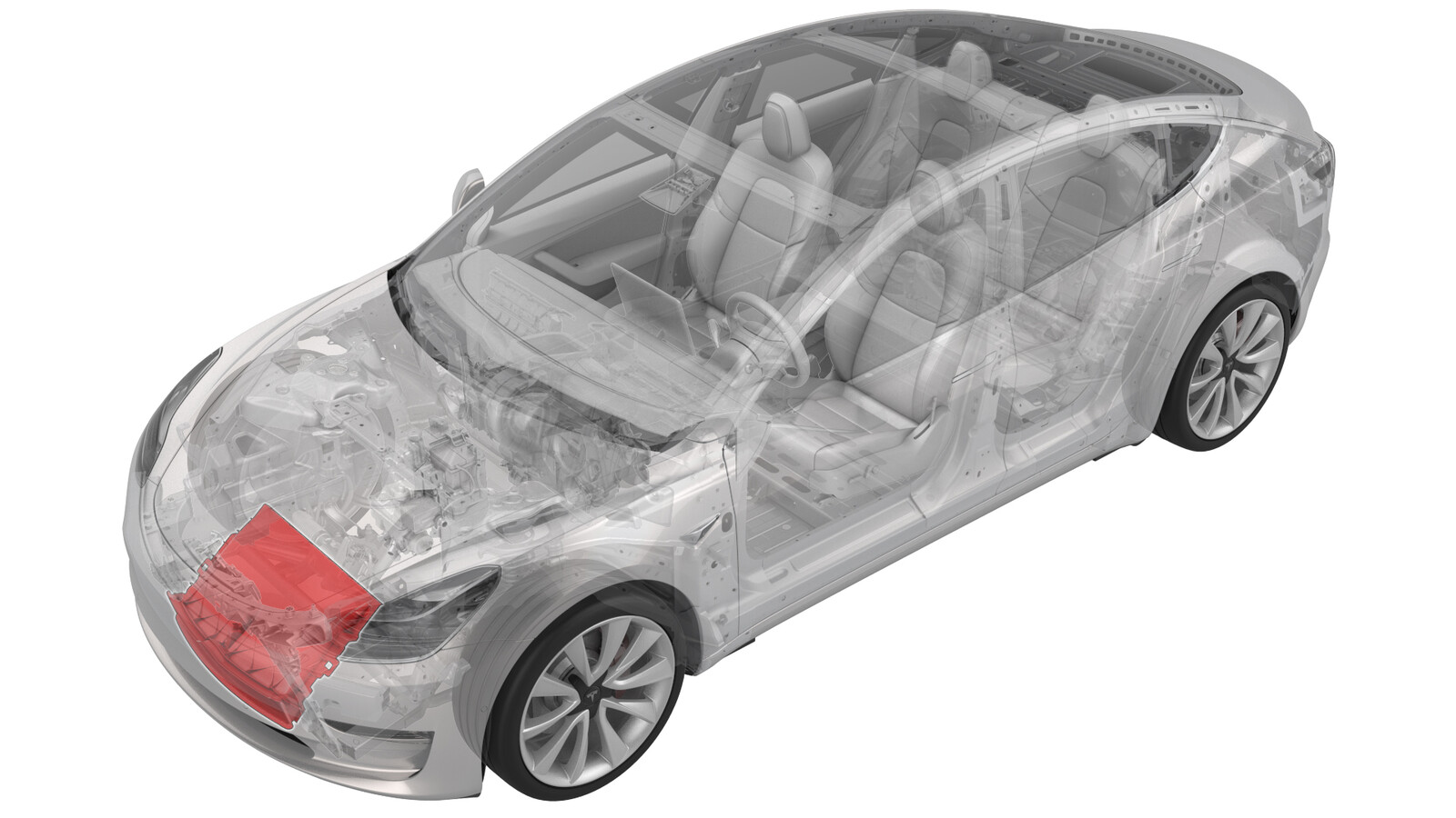
Active Grille Shutter (Heat Pump) (Remove and Replace)
 Correction code
18500612
0.72
NOTE: Unless otherwise explicitly
stated in the procedure, the above correction code and FRT reflect all of the work
required to perform this procedure, including the linked procedures. Do not stack correction codes unless
explicitly told to do so.
NOTE: See Flat Rate
Times to learn more about FRTs and how they are created. To provide feedback on
FRT values, email ServiceManualFeedback@tesla.com.
NOTE: See Personal Protection to make sure wearing proper PPE when
performing the below procedure. See Ergonomic Precautions for safe and healthy working practices.
- 2023-11-13: Updated the whole procedure according to the latest validation.
| Description | Torque Value | Recommended Tools | Reuse/Replace | Notes |
|---|---|---|---|---|
| LH and RH bolts (x2) that attach the cooling fan module assembly to the front end carrier |
 10 Nm (7.4 lbs-ft) |
|
Reuse |
Remove
- Put the vehicle on a 2-post lift.
- Open the LH front door and lower the LH front window.
- Remove the underhood storage unit. See Underhood Storage Unit (Remove and Replace).
- Disconnect the LV power. See 12V/LV Power (Disconnect and Connect).
-
Release the connector lock, and then disconnect the active grille shutter electrical connector.
CAUTIONDo not push down on the red tab. Pull the red tab to release the connector lock.
-
Remove the ambient temperature sensor cover from the active grille shutter, and then disconnect the sensor electrical connector.
- Remove the front aero shield panel. See Panel - Aero Shield - Front (Remove and Replace).
- Remove the front valance. See Valance - Front Fascia (Remove and Replace).
- Install towel to the front of subframe to protect the cooling fan in later steps.
-
With assistance supporting the cooling fan module assembly, remove the LH and RH bolts (x2) that attach the cooling fan module assembly to the front end carrier.
TIpUse of the following tool(s) is recommended:
- 8 mm socket
- Universal Joint 1/4in
Figure 1. LH Side Figure 2. RH Side - Lower the vehicle to a comfortable working height and set the lift onto locks.
-
Release the locking tabs (x14) that attach the active grille shutter to the cooling fan and shroud assembly, and then remove the active grille shutter.
Install
-
Install the active grille shutter onto the cooling fan and shroud assembly, and then fasten the locking tabs that attach the shutter to the assembly.
-
Raise the vehicle to a comfortable working height, and lower the lift onto locks.
CAUTION
Make sure there is an audible click of the locks on both sides before lowering, otherwise the vehicle may tilt to one side.
Make sure that the doors are clear of surrounding objects.
-
With assistance supporting the cooling fan module assembly, torque the LH and RH bolts (x2) that attach the cooling fan module assembly to the front end carrier.
 10 Nm (7.4 lbs-ft)TIpUse of the following tool(s) is recommended:
- 8 mm socket
- Universal Joint 1/4in
Figure 3. LH Side Figure 4. RH Side - Remove the towel from the front of subframe.
- Install the front valance. See Valance - Front Fascia (Remove and Replace).
- Install the front aero shield panel. See Panel - Aero Shield - Front (Remove and Replace).
- Lower the vehicle until tires are touching ground.
-
Connect the ambient temperature sensor electrical connector, and then install the sensor cover to the active grille shutter.
-
Engage the locking tab to connect the active grille shutter electrical connector.
- Connect LV power. See 12V/LV Power (Disconnect and Connect).
-
Perform the following
routine using Service Mode or Toolbox (see 0005 - Service Modes):
PROC_VCFRONT_X_LOUVER-CALIBRATIONvia Toolbox: (link)
NoteOnce complete, select the ‘X’ at the top right of the window to close.
-
Perform the following
routine using Service Mode or Toolbox (see 0005 - Service Modes):
TEST-SELF_VCFRONT_X_THERMAL-PERFORMANCEvia Toolbox: (link)via Service Mode: Thermal ➜ Actions ➜ Test Thermal Performancevia Service Mode Plus:
- Drive Inverter ➜ Front Drive Inverter Replacement ➜ Thermal System Test
- Drive Inverter ➜ Rear Drive Inverter Replacement ➜ Thermal System Test
- Drive Inverter ➜ Rear Left Drive Inverter Replacement ➜ Thermal System Test
- Drive Inverter ➜ Rear Right Drive Inverter Replacement ➜ Thermal System Test
- Drive Unit ➜ Front Drive Unit Replacement ➜ Thermal System Test
- Drive Unit ➜ Rear Drive Unit Replacement ➜ Thermal System Test
NoteOnce complete, select the ‘X’ at the top right of the window to close. - Disable Service Mode. See Service Mode.
- Install the underhood storage unit. See Underhood Storage Unit (Remove and Replace).
- Raise the LH front window and close the LH front door.
- Remove the vehicle from the lift.