Suspension - Rear (Check Torque)
Correction code 31039000 0.30 NOTE: Unless otherwise explicitly stated in the procedure, the above correction code and FRT reflect all of the work required to perform this procedure, including the linked procedures. Do not stack correction codes unless explicitly told to do so. NOTE: See Flat Rate Times to learn more about FRTs and how they are created. To provide feedback on FRT values, email ServiceManualFeedback@tesla.com. NOTE: See Personal Protection to make sure wearing proper PPE when performing the below procedure. See Ergonomic Precautions for safe and healthy working practices.
Equipment:
- 1135103-00-A Tool, Spring Compressor, Hook, Model 3
- 1081765-00-A 3/4 Ton Underhoist Stand
- 1063141-00-A 1/2 Ton Economy Transmission Jack
- 1137855-00-A Tool, Rear Ride Height Torque, Model 3
- 1459409-00-A ADAPTER, HUB JACK, MODEL 3
Torque Specifications
| Description | Torque Value | Recommended Tools | Reuse/Replace | Notes |
|---|---|---|---|---|
| Bolts that attach the LH and RH rear suspension covers to the vehicle |
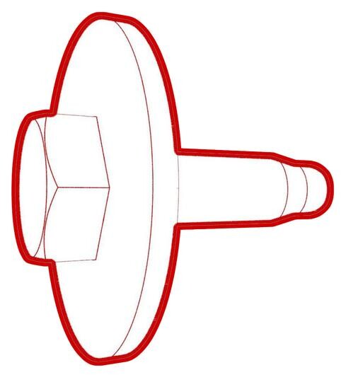 6 Nm (4.4 lbs-ft) |
|
||
| Bolts (x3) that attach the LH and RH shear plates to the HV battery |
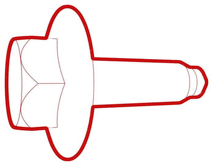 35 Nm (25.8 lbs-ft) 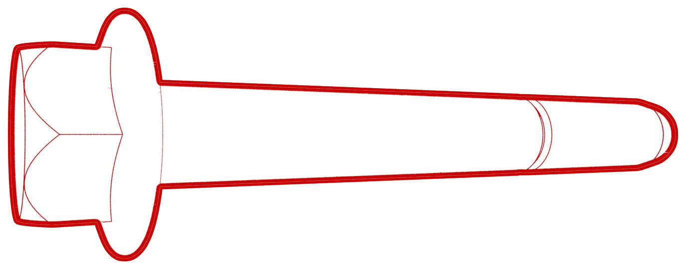 130 Nm (95.9 lbs-ft) |
|
||
| Nut that attaches the LH rear lower fore link to the rear subframe |
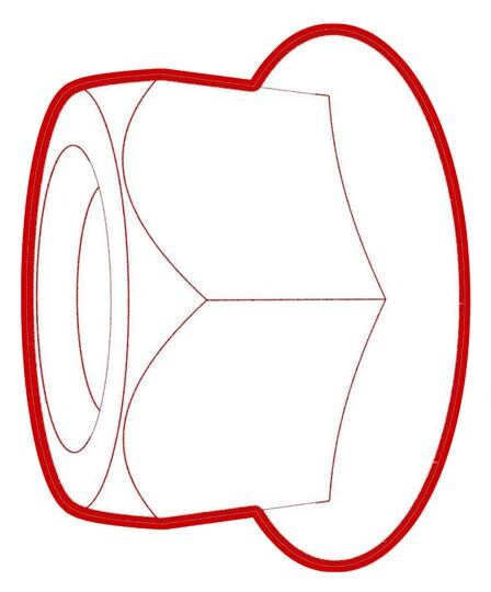 76 Nm (56.0 lbs-ft) |
|
||
| Nut that attaches the LH rear lower fore link to the knuckle |
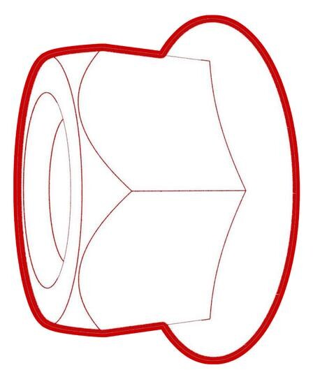 76 Nm (56.0 lbs-ft) |
|
||
| Nut that attaches the rear stabilizer bar to the LH stabilizer bar link |
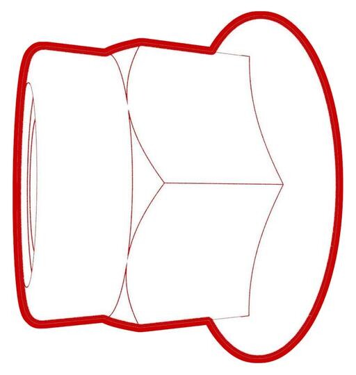 55 Nm (40.6 lbs-ft) |
|
||
| Nut that attaches the LH stabilizer bar link to the knuckle |
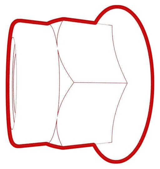 55 Nm (40.6 lbs-ft) |
|
||
| Nut that attaches the LH toe link to the rear subframe |
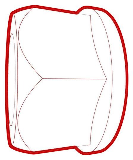 85 Nm (62.7 lbs-ft) |
|
||
| Nut that attaches the LH toe link to the knuckle |
 76 Nm (56.0 lbs-ft) |
|||
| Nut that attaches the LH rear lower aft link to the rear subframe |
 115 Nm (84.8 lbs-ft) |
|
||
| Nut that attaches the LH rear lower aft link to the knuckle |
 115 Nm (84.8 lbs-ft) |
|
||
| Nut that attaches the LH rear damper assembly to the LH lower aft link |
 115 Nm (84.8 lbs-ft) |
|||
| Nut that attaches the LH rear upper fore link to the rear subframe |
 76 Nm (56.0 lbs-ft) |
|
||
| Nut that attaches the LH rear upper fore link to the knuckle |
 76 Nm (56.0 lbs-ft) |
|||
| Nut that attaches the LH rear upper aft link to the rear subframe |
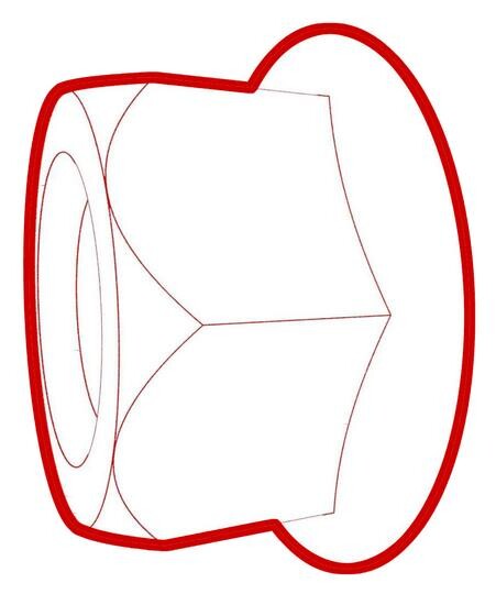 134 Nm (98.8 lbs-ft) |
|
||
| Nut that attaches the LH rear upper aft link to the knuckle |
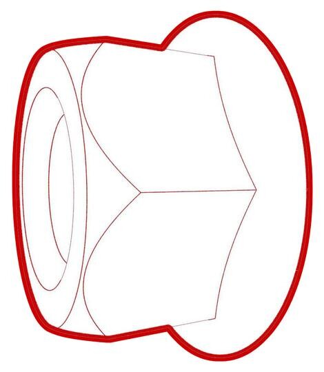 134 Nm (98.8 lbs-ft) |
|||
| Bolts that attach the rear diffuser to the body |
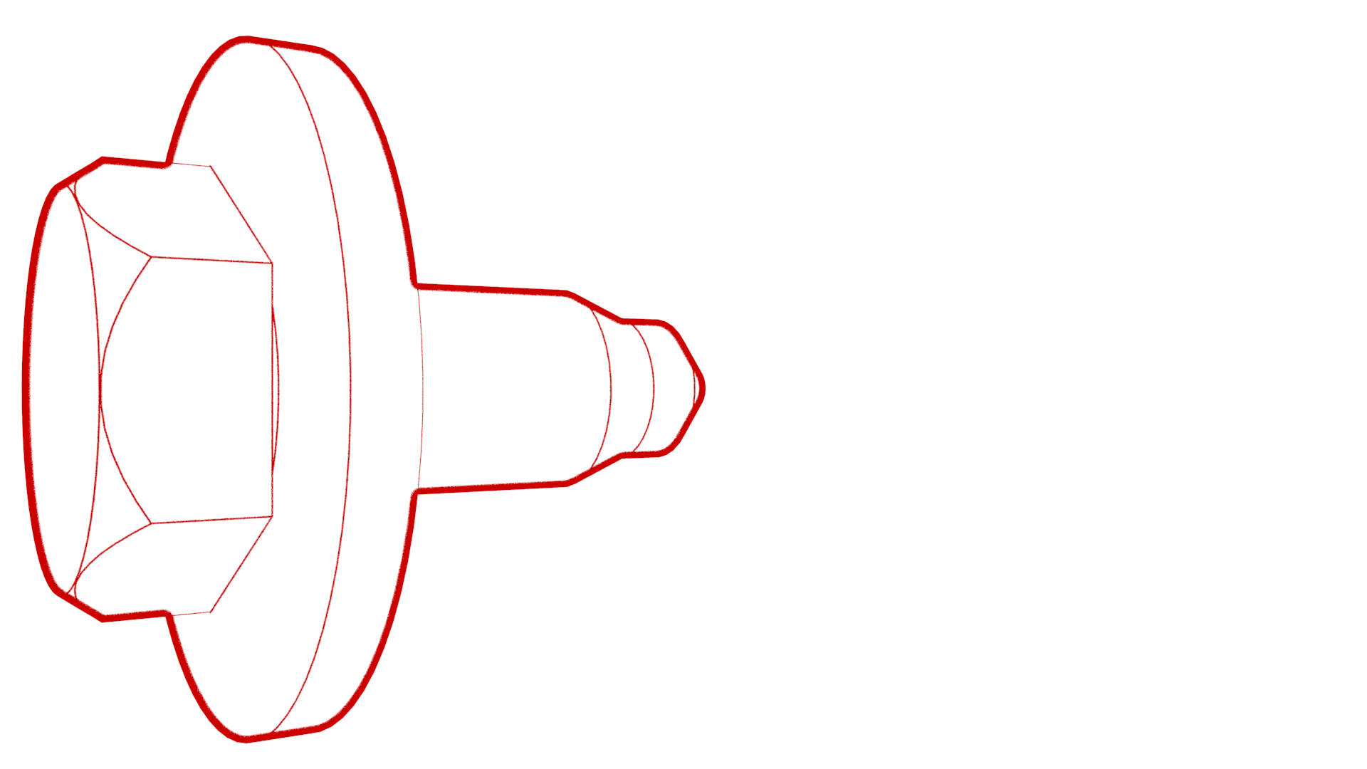 4 Nm (2.9 lbs-ft) |
|
Procedure
- Remove both rear wheels. See Wheel Assembly (Remove and Install).
- Remove the mid aero shield panel. See Panel - Aero Shield - Rear (Remove and Replace).
-
Remove the bolts that attach
the LH and RH rear suspension covers, and then remove the covers from the
vehicle.
 6 Nm (4.4 lbs-ft)TIpUse of the following tool(s) is recommended:
- 10 mm socket
- 2 in extension
-
Remove the bolts (x4) that attach the front of the rear diffuser to the
body.
- Position the transmission jack to support the front beam of the rear subframe.
-
Release the fir tree clips (x2) that attach the coolant hoses to the LH and RH shear plates.
-
Remove the bolts (x3) that
attach the LH and RH shear plates to the HV battery, remove the shear
plates, and then reinstall the long bolts directly into the rear
subframe.
 35 Nm (25.8 lbs-ft)
 130 Nm (95.9 lbs-ft)TIpUse of the following tool(s) is recommended:
- 13 mm socket
- 21 mm socket
- 3 in extension
- 6 in extension
- Remove the transmission jack out from under the front beam of the rear subframe.
-
Remove the center clip that attaches the LH and RH wheel liners to the body.
-
Install the spring
compressor to the rear LH spring and compress the spring so that is it loose
in the suspension.
NoteThe lowest hook of the spring compressor goes under the coil at the strut. The highest hook of the spring compressor goes over the coil at the HV battery. The spring compressor lead screw should center to, and pass through, the opening in the body.
-
Remove the bolt that attaches the brake rotor to the hub.
NoteUse of the following tool(s) is recommended:
- 10 mm socket
- 2 in extension
-
Install the hub jack adapter onto the LH rear hub and hand-tighten the lug
nuts.
-
Use an underhoist stand to support the hub jack adapter.
NoteUse the rear ride height torque gauge to verify that the rear suspension is set to ride height specifications and adjust the support stand or spring compressor tool , if necessary.
-
Measure the distance between
the bottom of the quarter panel to the center of the rear axle to make sure
that the rear suspension is set to ride height: The distance should measure
378 mm.
-
Check the torque for the nut
that attaches the LH rear lower fore link to the rear subframe, and then
mark the nut with a paint pen.
 76 Nm (56.0 lbs-ft)TIpUse of the following tool(s) is recommended:
- 18 mm socket
- 18 mm combination wrench
- Flex head ratchet/flex head torque wrench
-
Check the torque for the nut
that attaches the LH rear lower fore link to the knuckle, and then mark the
nut with a paint pen.
 76 Nm (56.0 lbs-ft)TIpUse of the following tool(s) is recommended:
- 18 mm socket
- 18 mm ratcheting combination wrench
- Flex head ratchet/flex head torque wrench
-
Check the torque for the nut
that attaches the rear stabilizer bar to the LH stabilizer bar link, and
then mark the nut with a paint pen.
 55 Nm (40.6 lbs-ft)TIpUse of the following tool(s) is recommended:
- 15 mm socket
- 5 mm hex socket
- 15 mm flex head combination ratcheting wrench
- Flex head ratchet/flex head torque wrench
-
Check the torque for the nut
that attaches the LH stabilizer bar link to the knuckle, and then mark the
nut with a paint pen.
 55 Nm (40.6 lbs-ft)TIpUse of the following tool(s) is recommended:
- 15 mm socket
- 5 mm hex socket
- 15 mm flex head combination ratcheting wrench
- Flex head ratchet/flex head torque wrench
-
Check the torque for the nut
that attaches the LH toe link to the rear subframe, and then mark the nut
with a paint pen.
 85 Nm (62.7 lbs-ft)TIpUse of the following tool(s) is recommended:
- 18 mm deep socket
- 18 mm combination wrench
- Flex head ratchet/flex head torque wrench
-
Check the torque for the nut
that attaches the LH toe link to the knuckle, and then mark the nut with a
paint pen.
 76 Nm (56.0 lbs-ft)TIpUse of the following tool(s) is recommended:
 -
Check the torque for the nut
that attaches the LH rear lower aft link to the rear subframe, and then mark
the nut with a paint pen.
 115 Nm (84.8 lbs-ft)TIpUse of the following tool(s) is recommended:
- 21 mm socket
- 21 mm combination wrench
-
Check the torque for the nut
that attaches the LH rear lower aft link to the knuckle, and then mark the
nut with a paint pen.
 115 Nm (84.8 lbs-ft)TIpUse of the following tool(s) is recommended:
- 21 mm socket
- 21 mm ratcheting combination wrench
- Flex head ratchet/flex head torque wrench
-
Check the torque for the nut
that attaches the LH rear damper assembly to the LH lower aft link, and then
mark the nut with a paint pen.
 115 Nm (84.8 lbs-ft)TIpUse of the following tool(s) is recommended:
 -
Check the torque for the nut
that attaches the LH rear upper fore link to the rear subframe, and then
mark the nut with a paint pen.
 76 Nm (56.0 lbs-ft)TIpUse of the following tool(s) is recommended:
- 18 mm socket
- 18 mm combination wrench
- Flex head ratchet/flex head torque wrench
-
Check the torque for the nut
that attaches the LH rear upper fore link to the knuckle, and then mark the
nut with a paint pen.
 76 Nm (56.0 lbs-ft)TIpUse of the following tool(s) is recommended:
 -
Check the torque for the nut
that attaches the LH rear upper aft link to the rear subframe, and then mark
the nut with a paint pen.
 134 Nm (98.8 lbs-ft)TIpUse of the following tool(s) is recommended:
- 21 mm socket
- 21 mm combination wrench
-
Check the torque for the nut
that attaches the LH rear upper aft link to the knuckle, and then mark the
nut with a paint pen.
 134 Nm (98.8 lbs-ft)TIpUse of the following tool(s) is recommended:
 -
Remove the underhoist stand from underneath the LH rear suspension.
-
Remove the lug nuts that attach the hub jack adapter, and then remove the
hub jack adapter from the vehicle.
-
Install the bolt that attaches the LH rear brake rotor to the hub.
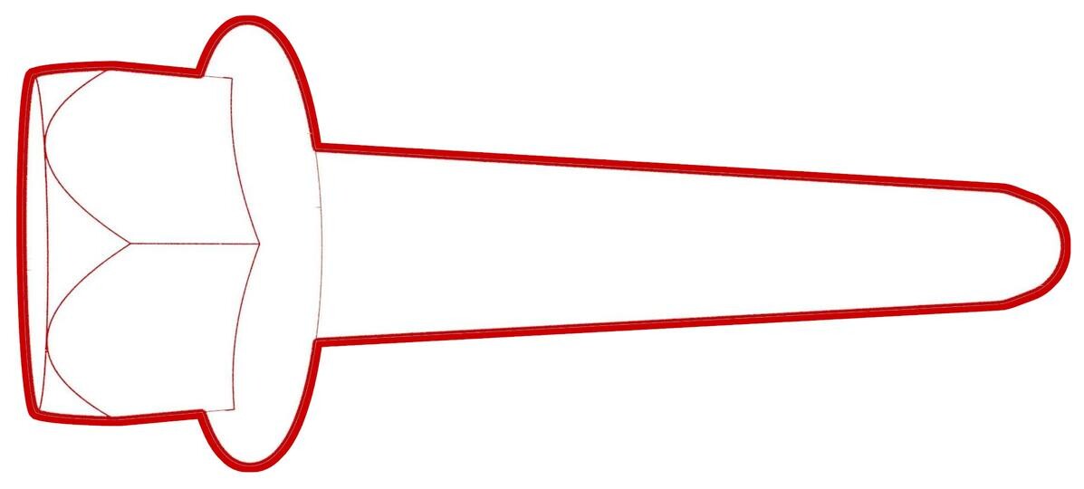 5 Nm (3.7 lbs-ft)NoteUse of the following tool(s) is recommended:
- 10 mm socket
- 2 in extension
- Remove the spring compressor from the rear LH spring.
- Repeat step 3 through step 29 on the RH side of the rear suspension.
- Position the transmission jack to support the front beam of the rear subframe.
-
Remove the long bolts (x2)
from the front of the rear subframe, install the LH and RH shear plates to
the subframe and HV battery, and then install the bolts (x3) that attach the
shear plates to the subframe and HV battery.
 35 Nm (25.8 lbs-ft)
 130 Nm (95.9 lbs-ft)TIpUse of the following tool(s) is recommended:
- 13 mm socket
- 21 mm socket
- 3 in extension
- 6 in extension
-
Fasten the fir tree clips (x2) that attach the coolant hoses to the LH and RH shear plates.
- Remove the transmission jack out from under the front beam of the rear subframe.
-
Install the center clip that attaches the LH and RH wheel liners to the body.
-
Install the bolts (x4) that attach the front of the rear diffuser to the
body.
 4 Nm (2.9 lbs-ft)TIpUse of the following tool(s) is recommended:
- 10 mm socket
-
Install the LH and RH rear
suspension covers.
 6 Nm (4.4 lbs-ft)TIpUse of the following tool(s) is recommended:
- 10 mm socket
- 2 in extension
- Install the mid aero shield panel. See Panel - Aero Shield - Rear (Remove and Replace).
- Install both rear wheels. See Wheel Assembly (Remove and Install).