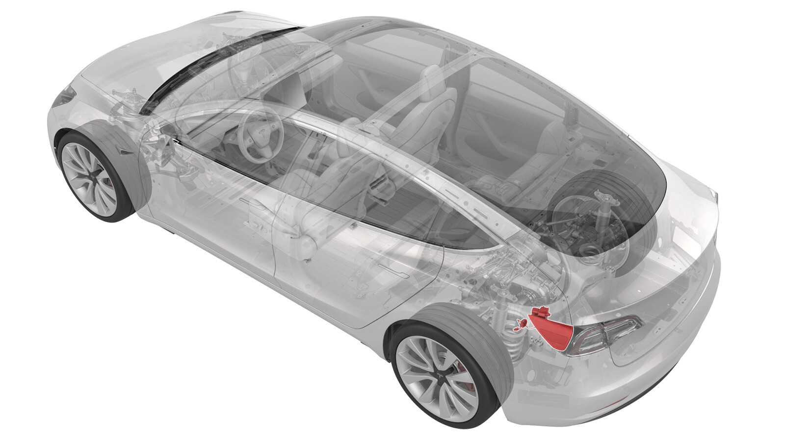
Door Assembly - Charge Port (EMEA) (Remove and Replace)
 Correction code
44015302
0.66
NOTE: Unless otherwise explicitly
stated in the procedure, the above correction code and FRT reflect all of the work
required to perform this procedure, including the linked procedures. Do not stack correction codes unless
explicitly told to do so.
NOTE: See Flat Rate
Times to learn more about FRTs and how they are created.
NOTE: See Personal Protection to make sure wearing proper PPE when
performing the below procedure. NOTE: See Ergonomic Precautions for safe and healthy working
practices.
Correction code
44015302
0.66
NOTE: Unless otherwise explicitly
stated in the procedure, the above correction code and FRT reflect all of the work
required to perform this procedure, including the linked procedures. Do not stack correction codes unless
explicitly told to do so.
NOTE: See Flat Rate
Times to learn more about FRTs and how they are created.
NOTE: See Personal Protection to make sure wearing proper PPE when
performing the below procedure. NOTE: See Ergonomic Precautions for safe and healthy working
practices.
- 2023-10-27: Update charge port to body bolt torque to 9 Nm.
- 2023-06-06: Updated Charge Identifier Label TPN from 1691926-00-A to 1691926-00-B and updated related illustration.
- 2023-05-24: Removed the vehicle electrical isolation procedure.
Equipment:
- 1076921-01-B Insulation Multimeter, Fluke 1508
- 1130480-00-A Test Probes, Slim, Fluke TP38
Only
technicians who have completed all required certification courses are permitted to
perform this procedure. Tesla recommends third party service provider technicians
undergo equivalent training before performing this procedure. For more information on
Tesla Technician requirements, or descriptions of the subject matter for third parties,
see HV Certification Requirements. Proper personal protective equipment (PPE) and insulating HV
gloves with a minimum rating of class 0 (1000V) must
be worn at all times a high voltage cable, busbar, or fitting is handled. Refer to Tech Note TN-15-92-003, High Voltage Awareness
Care Points
for additional safety
information.
Remove all jewelry (watches, bracelets, rings, necklaces, earrings, ID tags, piercings, etc.) from your person, and all objects (keys, coins, pens, pencils, tools, fasteners, etc.) from your pockets before performing any procedure that exposes you to high voltage.
Proper personal protective equipment (PPE) is required to perform this procedure:
- High voltage insulating gloves
- Leather glove protectors
- High voltage glove tester
- Safety glasses
- Electrical hazard rated safety shoes
A glove inflator is the only recommended way to test HV gloves. Both HV gloves must pass testing before beginning this procedure. If either glove does not pass the air check, discard the pair.
Make sure that the HV gloves are not expired. HV gloves can be used up to 12 months after the testing date printed on the glove, but only 6 months after first use even if the gloves are still within the 12-month period.
Remove
- Open all doors and windows.
- Remove the rear underhood apron. See Underhood Apron - Rear (Remove and Replace).
- Open the trunk.
-
Apply masking tape around
the charge port area.
- Move the driver and front passenger seats fully forward.
- Remove the 2nd row lower seat cushion. See Seat Cushion - Lower - 2nd Row (Remove and Replace).
- Disconnect 12V power. See 12V/LV Power (Disconnect and Connect).
- Perform the charge port voltage check procedure. See Charge Port Voltage Check.
- Remove the trunk floor trim. See Trim - Floor - Trunk (Remove and Replace).
- Remove the trunk sill trim panel. See Trim - Sill - Trunk (Remove and Replace).
- Remove the trunk garnish. See Garnish - Trunk (Remove and Replace).
- Disconnect the LH liftgate task light connector.
- Release the edge of the trunk carpet, and then move the LH trunk side trim aside.
- Remove the LH taillight. See Taillight - LH (Remove and Replace).
-
Release the edge clip that
attaches the LV electrical harness to the charge port closeout panel.
-
Slightly pull on the
closeout panel. At the same time, insert a plastic trim tool inwards to
start releasing the lower clips, and then pull the closeout panel towards
the front of the vehicle while releasing the remaining clips.
-
Remove the bolt that
attaches the charge port harness bracket and ground cable to the body.
-
Pull the manual release
cable up and away from the cable hold down clip, or pull up the cable
vertically away from the charge port assembly.
-
Remove the bolts that attach
the charge port to the body.
-
Disconnect the Low Voltage
(LV) electrical connectors from the charge port ECU.
-
Pull the charge port
assembly away from the body for access.
-
Release the charge port door
harness grommet from the body
-
Release the lower clips that
attach the charge port door assembly to the vehicle, then push the bottom of
the assembly out, and then remove the assembly from the vehicle.
NoteTo ease the removal of the charge port door assembly:
- Pull the assembly towards the rear of the vehicle.
- When the assembly reaches the rear of the quarter panel, pull the assembly to clear the actuator mechanism, and then pull the assembly out and away from the body.
NoteManipulation of the charge port door assembly might be necessary to completely remove the assembly from the body.
Install
-
Install the charge port door
assembly on the vehicle: Pivot the assembly so that the actuator mechanism
clears underneath the quarter panel, and then slide the assembly forward
towards the rear door.
NoteManipulation of the charge port door assembly might be necessary to fully align the assembly to the rear quarter.
-
Push the charge port door
assembly electrical harness through the opening, and then attach the charge
port door assembly with lower clips (x2).
-
Install the charge port door
grommet on the body.
WarningMake sure the harness is routed out, and the adhesive pad with zip tie is properly mounted if it is installed.
- Move the charge port assembly into position for installation.
-
Connect the low voltage
charge port ECU electrical connectors.
-
Install the bolts that
attach the charge port to the body.
 9 Nm (6.6 lbs-ft)
 - Insert the manual release cable back into the locking tab; push down on the release back to secure it into the locking tab.
-
Install the bolt that
attaches the charge port harness bracket and ground cable to the body.
 6 Nm (4.4 lbs-ft)
 -
Install the clips that
attach the charge port closeout panel.
-
Install the edge clip that
attaches the LV harness to the charge port closeout panel.
- Install the LH taillight. See Taillight - LH (Remove and Replace).
-
Install the LH trunk
stop.
- Remove the masking tape from the charge port door area.
- Move the LH trunk side trim back into position, and then install the clips (x2) that attach the side trim to the vehicle.
- Connect the LH liftgate task light connector.
- Install the trunk garnish. See Garnish - Trunk (Remove and Replace).
- Install the trunk sill trim panel. See Trim - Sill - Trunk (Remove and Replace).
- Install the trunk floor trim. See Trim - Floor - Trunk (Remove and Replace).
- Close the trunk.
- Reconnect 12V power. See 12V/LV Power (Disconnect and Connect).
- Install the 2nd row lower seat cushion. See Seat Cushion - Lower - 2nd Row (Remove and Replace).
- Move the driver and front passenger seats back to their original position.
-
Verify the operation of the
charging system:
NoteUse the customer's charging equipment, if present.
-
Europe only: install a CKL
charging identifier label (1691926-00-B) on the face plate of the charge
port assembly as illustrated, if one was present on the original part.
- Install the rear underhood apron. See Underhood Apron - Rear (Remove and Replace).
- Close the hood and all doors and windows.