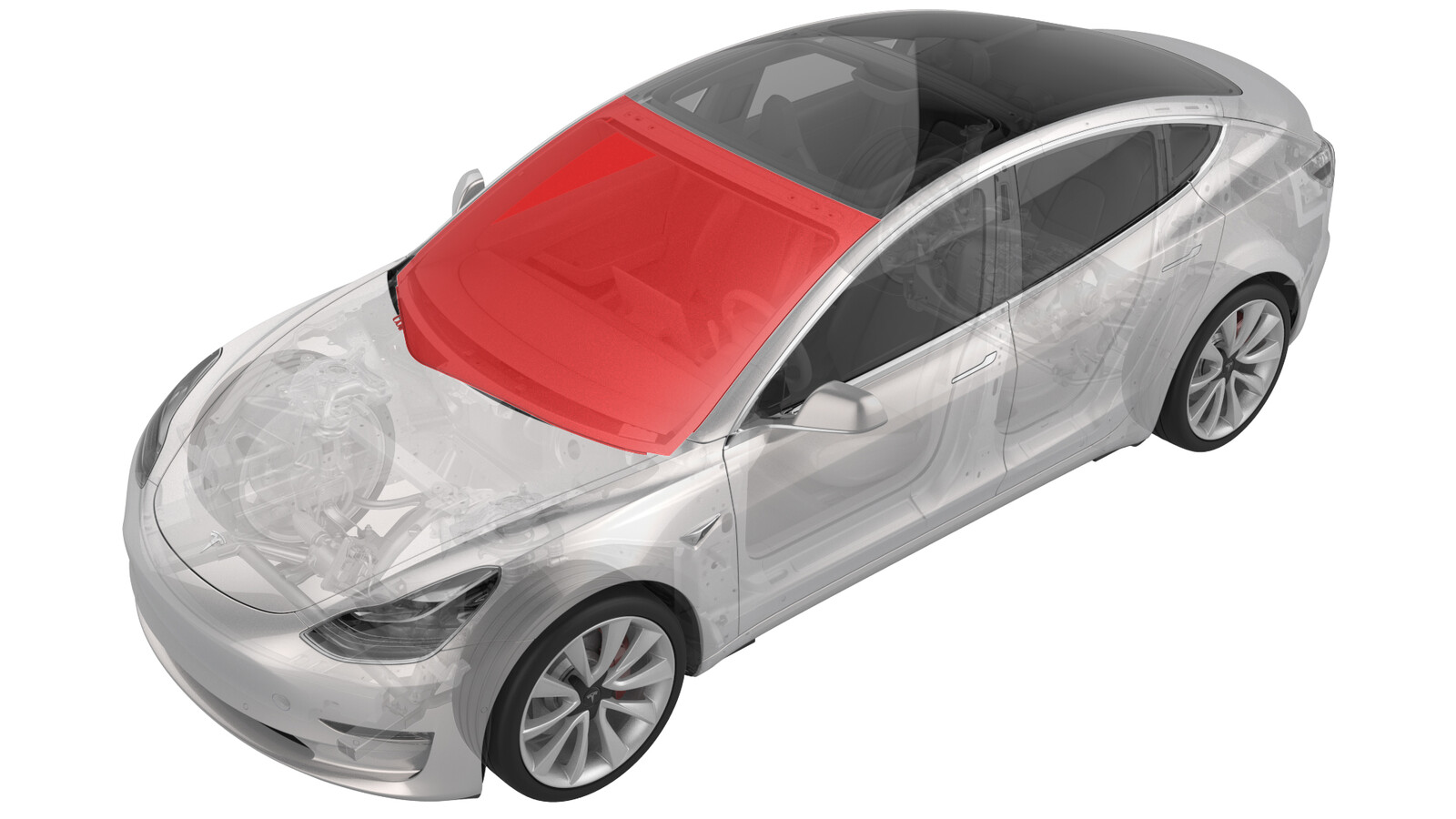
Windshield (Reuse Humidity and Temperature Sensor) (Remove and Replace)
 Correction code
10200312
2.04
NOTE: Unless otherwise explicitly
stated in the procedure, the above correction code and FRT reflect all of the work
required to perform this procedure, including the linked procedures. Do not stack correction codes unless
explicitly told to do so.
NOTE: See Flat Rate
Times to learn more about FRTs and how they are created.
NOTE: See Personal Protection to make sure wearing proper PPE when
performing the below procedure. NOTE: See Ergonomic Precautions for safe and healthy working
practices.
Correction code
10200312
2.04
NOTE: Unless otherwise explicitly
stated in the procedure, the above correction code and FRT reflect all of the work
required to perform this procedure, including the linked procedures. Do not stack correction codes unless
explicitly told to do so.
NOTE: See Flat Rate
Times to learn more about FRTs and how they are created.
NOTE: See Personal Protection to make sure wearing proper PPE when
performing the below procedure. NOTE: See Ergonomic Precautions for safe and healthy working
practices.
- 2025-03-26: Added note and caution to make sure vehicle is parked on a flat place.
- 2024-12-10: Added new caution about Pre-Installation Glass Inspection service requirements.
- 2023-08-02: Fixed small errors in the procedure.
- 2023-05-15: Added Pre-GCL and GCL windshield heater connector and jumper harness disconnect/connect direction.
Remove
- Open both front doors and lower all windows.
- Remove the cowl screen panel. See Panel - Cowl Screen (Remove and Replace).
-
Disconnect the electrical harness from the windshield heater connector.
- Remove the driver sun visor check base. See Check Base - Sun Visor - LH (Remove and Replace).
- Remove the forward facing triple camera. See Camera - Triple - Forward Facing (Remove and Replace).
- Remove the GPS antenna. See Antenna - GPS (Remove and Replace).
- Remove the LH mid A-pillar trim. See Trim - A-Pillar - Middle - LH (Remove and Replace).
- Remove the LH upper A-pillar trim. See Trim - A-Pillar - Upper - LH (Remove and Replace).
- Remove the LH sun visor. See Sun Visor - LH (Remove and Replace).
- Remove the LH sun visor check base. See Check Base - Sun Visor - LH (Remove and Replace).
- Repeat steps 7 through 10 on the RH side of the vehicle.
-
Release the clips (x4) that attach the front of the headliner to the body, and then separate the headliner from the body.
-
Release the clips (x6) that attach the windshield harness to the fastener track, and then release the harness from the track.
-
Remove the windshield fastener track.
-
Prepare the WRD Spider 3 glass removal kit.
TIpUse of the following tool(s) is recommended:
- WRD Spider 3 - 1571168-00-A
-
Secure the wire to the starter tool and push the tool through the urethane at the RH lower side of the windshield assembly.
CAUTIONUse the guard to prevent damage to the dash pad while using the starter tool.CAUTIONEnsure the vehicle is parked on a flat surface for the entirety of the curing process.
-
Release the line from the starter tool and wrap the line around the exterior of the windshield.
NotePull the line away from the starter tool. Make sure enough length is pulled through.NoteVerify the line sits underneath the glass.
-
Attach the anchor point to the exterior of the windshield near the starting point of the handle tool, and then secure the line to the anchor.
-
Secure the interior side of the line to the Spider cutting tool.
NoteFollow the instructions on the Spider tool. Feed the line through the opening of the cutting tool and tie a knot to secure the line in place. If the spindle is not turned the proper direction, the cutting tool will be damaged.
-
Secure the Spider cutting tool to the interior side of the windshield.
NoteNote the orientation of the cutting line. Make sure the line wraps over the large pulley and holds a 90 degree angle.
-
Secure the angle driver to the electric drill.
-
Turn the spindle on the cutting tool with the drill to start remove the windshield.
NoteMove the cutting tool as needed, keeping the line close to a 90 degree angle.CAUTIONWhen passing the VIN plate, use the guard to guide the line over the plate to prevent damage.CAUTIONTake special care in the four areas identified that have overlapping panels and/or tabs to prevent damage.
- Attach suction cups (x4) to the LH and RH sides of the windshield assembly.
-
With an assistant, remove the windshield assembly from the vehicle.
-
Remove the suction cups from the windshield assembly.
-
Use a razor blade to remove the old urethane from the windshield flange on the vehicle.
WarningWear cut-resistant gloves and safety glasses when performing this step to avoid personal injury.
-
Remove the screws (x2) that attaches the temperature and humidity sensor to the windshield bracket, and then release the sensor from the bracket.
 0.12 Nm (1 lbs-in)CAUTIONEnsure the correct Phillips screwdriver is used. If the screwdriver is too large the fastener will round out.CAUTIONThe fasteners are very small. Take care not to drop or misplace them.TIpUse of the following tool(s) is recommended:
- PH00 screwdriver
-
Use a heat gun on the outside of the windshield to release heat the adhesive as shown, and then gently pry the board away from the bracket as heat is applied to remove the sensor from the bracket.
NoteAngle the board up and over the plastic alignment pin, and then move the board upward to clear the retaining plastic.
Replace Graphene Block
-
Prepare the ESD kit.
CAUTIONImproper use of the ESD kit can result in damage to components.NoteRefer to TN-14-92-003, “Electrostatic Discharge Tool” for more information.
-
Place the ESD mat flat onto a workbench so that the button connector is closest to the grounding point (outlet, vehicle chassis, etc.)
-
Snap the button connector on the ground cord to the button connector on the ESD mat.
NoteMake sure the connector is securely fastened to the ESD mat.
-
Remove the alligator clip adapter from the end of the wrist strap to expose the banana plug.
-
Connect the banana plug on the wrist strap to the ground cord.
-
Connect the ground cord to a ground source. Choose from:
- Per TN-14-92-003-R1, Service Centers with NEMA 5-15 outlets, perform the following:
- Plug the ground indicator into the outlet and confirm the 2 lights on the right are lit.
- Remove the alligator clip adapter from the end of the ground cord to expose the banana plug.
- Plug the banana plug on the ground cord into the ground indicator.
- Service Centers with grounded, non-NEMA 5-15 outlets, perform the following:
- Plug the appropriate adapter into the outlet.NoteService Centers with grounded, non-NEMA 5-15 outlets need to supply an adapter suitable to connect the ground indicator to their regional outlet type. If you are unable to obtain an adapter, contact ServiceTooling@teslamotors.com for assistance.
- Plug the ground indicator into the adapter and confirm the 2 lights on the right are lit.
- Remove the alligator clip adapter from the end of the ground cord to expose the banana plug.
- Plug the banana plug on the ground cord into the ground indicator.
- Plug the appropriate adapter into the outlet.
- Service Centers with non-grounded outlets, perform the following:
- Clip the alligator clip adapter on the ground cord onto any unpainted metal part of the vehicle.
- Per TN-14-92-003-R1, Service Centers with NEMA 5-15 outlets, perform the following:
-
Put on the ESD wrist strap.
-
Remove the graphene foam block from the temperature and humidity sensor.
NoteApply heat to the area around the adhesive, and then use tweezers to gently lift the graphene foam block up to release it.
-
Use an IPA wipe to clean the area where the temperature and humidity sensor foam block will rest.
NoteAllow 1 minute of dry time.
-
Secure the foam block locator tool onto the temperature and humidity sensor.
NoteAlign the datum on the tool with the alignment hole in the board.TIpUse of the following tool(s) is recommended:
- M3 THS Foam Fixture - 1727102-00-A
-
Using tweezers, carefully install the graphene block onto the temperature and humidity sensor.
NoteMake sure the graphene block is installed completely inside of the gold square and that the hole closest to the chip remains uncovered.TIpUse of the following tool(s) is recommended:
- Tweezers - 1126453-00-A
- Remove the ESD wrist strap.
Install
- Clean the windshield as needed. Take special caution to the forward-facing camera area to ensure a clear view of the forward-facing camera. See .
- Place the new windshield on a support stand with the windshield bracket facing up.
-
Install the temperature and humidity sensor onto the windshield bracket.
NoteMake sure the blue tape is removed from the foam block before installation.NoteMake sure the windshield is completely dry before attempting to install; the foam block will not stick if the windshield is wet.NoteSlide the end of board into the retaining plastic, and then align the hole on the board with the plastic alignment pin.
-
Install the screws (x2) that attaches the temperature and humidity sensor to the windshield bracket.0.12 Nm (1 lbs-in)CAUTIONMake sure to use the correct Phillips screwdriver.CAUTIONMake sure the fasteners are not over torqued as they are VERY delicate and will strip out very easily.CAUTIONThe fasteners are very small. Take care not to drop or misplace them.TIpUse of the following tool(s) is recommended:
- PH00 screwdriver
- Attach suction cups (x4) to the LH and RH sides of the windshield assembly.
- Clean the urethane path on the vehicle with an isopropyl alcohol (IPA) wipe. Allow the surface to dry before continuing to the next step.
-
Apply urethane primer to the vehicle body and windshield along the urethane path and in areas that were damaged during removal of the windshield assembly.
CAUTIONBe careful not to damage the headliner during application.NoteAllow the primer to dry for at least 2 minutes.
-
Apply urethane to the windshield following the original path.
CAUTIONBe careful not to damage the headliner during application.NoteMake sure that the urethane bead has a triangular cross-section of approximate width 8 mm and height 13 mm.
- With an assistant, install the new windshield assembly onto the vehicle, but do not set it yet.
- Check the gap and flush of the windshield assembly to the body before fully seating the windshield assembly.
- Fully seat the windshield assembly, check the gap and flush, and adjust if necessary.
- Apply masking tape to attach the windshield assembly to the body while the urethane cures.
- Remove the suction cups from the windshield.
-
Install the GPS antenna into the windshield bracket, and then install the screw that attaches the antenna to the bracket.
 1 Nm (.7 lbs-ft)
 -
Install the windshield electrical harness to the windshield bracket, and then install the screw that attaches the harness to the bracket.1 Nm (.7 lbs-ft)
-
Connect the windshield electrical harness to the GPS antenna connector.
-
Connect the windshield electrical harness to the humidity and temperature sensor connector.
- Install the forward facing triple camera. See Camera - Triple - Forward Facing (Remove and Replace).
- Install the triple camera hood. See Glare Shield (Remove and Replace).
-
Position the windshield harness to the fastener track, and then secure the clips (x6) that attach the harness to the fastener track.
-
Secure the clips (x4) that attach the front of the headliner to the body.
NoteReseat the primary seal near the A-pillar and B-pillar to the headliner.
- Install the LH upper A-pillar trim. See Trim - A-Pillar - Upper - LH (Remove and Replace).
- Install the LH mid A-pillar trim. See Trim - A-Pillar - Middle - LH (Remove and Replace).
- Install the LH sun visor. See Sun Visor - LH (Remove and Replace).
- Install the LH sun visor check base. See Check Base - Sun Visor - LH (Remove and Replace).
- Repeat steps 22 through 25 on the RH side of the vehicle.
-
Connect the interior camera connector, and then install the clips that attach the upper quad camera cover to the vehicle.
-
Connect the electrical harness to the windshield heater connector.
- Install the cowl screen panel. See Panel - Cowl Screen (Remove and Replace).
- Perform the forward facing camera pitch verification. See Camera - Forward Facing (Pitch Verification).
-
Remove the masking tape after the urethane has cured.
CAUTIONDo not drive the vehicle until the adhesive manufacturer’s recommended minimum drive-away time has passed. Dow Betaseal Express has a drive-away time of 1 hour minimum in temperatures of 0˚F (-18˚C) or warmer. If necessary, leave the tape applying pressure to the glass on the vehicle and advise the customer that they can remove it after 24 hours. Additionally, advise the customer that they should avoid high driving speeds and speed bumps for the next 24 hours.