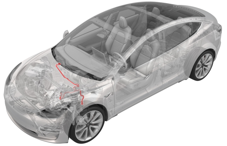
Hose - Chiller to Car Computer and HV Battery Supply Manifold (RWD) (RHD) (Remove and Replace)
 Correction code
18301212
1.08
NOTE: Unless otherwise explicitly
stated in the procedure, the above correction code and FRT reflect all of the work
required to perform this procedure, including the linked procedures. Do not stack correction codes unless
explicitly told to do so.
NOTE: See Flat Rate
Times to learn more about FRTs and how they are created.
NOTE: See Personal Protection to make sure wearing proper PPE when
performing the below procedure. NOTE: See Ergonomic Precautions for safe and healthy working
practices.
Correction code
18301212
1.08
NOTE: Unless otherwise explicitly
stated in the procedure, the above correction code and FRT reflect all of the work
required to perform this procedure, including the linked procedures. Do not stack correction codes unless
explicitly told to do so.
NOTE: See Flat Rate
Times to learn more about FRTs and how they are created.
NOTE: See Personal Protection to make sure wearing proper PPE when
performing the below procedure. NOTE: See Ergonomic Precautions for safe and healthy working
practices.
Equipment:
- 1119171-00-A Plug,Car Computer Fluid Port
- 1135762-00-A Kit, Svc Plug, Cooling Hose, Model 3
Remove
- Remove the front aero shield panel. See Panel - Aero Shield - Front (Remove and Replace).
- Remove the cowl screen panel. See Panel - Cowl Screen (Remove and Replace).
- Disconnect 12V power. See 12V/LV Power (Disconnect and Connect).
- Position a coolant drain container under the front of the vehicle.
-
Disconnect the vent tube
hose from the LH side of the battery and release the vent tube hose clip
from the battery bracket.
-
Disconnect the coolant
temperature sensor connector from the chiller to car computer and HV battery
supply manifold hose.
-
Release the clip that
attaches the 12V battery vent hose to the chiller to car computer and HV
battery supply manifold hose.
-
Release the clip that
attaches the electrical harness to the chiller to car computer and HV
battery supply manifold hose.
-
Place an absorbent towel
under the car computer coolant connections, as shown.
-
Release the clip that
connects the LH car computer coolant hose to the car computer coolant port,
and then disconnect the hose.
-
Release the clip that
connects the RH car computer coolant hose to the car computer coolant port,
and then disconnect the hose.
- Install the car computer coolant plug.
-
Place an absorbent towel
under the chiller.
-
Release the clip that
connects the hose to the chiller and EXV assembly, and then disconnect the
hose from the chiller.
-
Plug the chiller coolant
outlet.
- Fully raise the vehicle, and then position a coolant drain container underneath the LH front side of the HV battery.
-
Release the clips that
attach the chiller to car computer and HV battery supply manifold hose to
the vehicle.
NoteThe number of clips may vary depending on vehicle production date.
-
Release the clip that
connects the chiller tocar computer and HV battery supply manifold hose to
the HV battery supply manifold.
-
Plug the HV battery supply
manifold.
-
Release the clip that
attaches the chiller to car computer and HV battery supply manifold hose to
the 12V battery bracket.
-
Release the clip that
attaches the chiller to car computer and HV battery supply manifold hose to
the 12V battery beam.
-
Release the clips that
attach the chiller tocar computer and HV battery supply manifold hose to the
vehicle.
-
Remove the chiller to car
computer and HV battery supply manifold hose from the vehicle.
Install
Installation procedure is the reverse of removal, except for the following:
-
Before installing the
underhood storage unit, fill the superbottle to the appropriate level.
NoteMake sure that the fluid level is 5 mm above the MAX line.
-
Perform the following
routine using Service Mode or Toolbox (see 0005 - Service Modes):
TEST_VCFRONT_X_THERMAL-COOLANT-AIR-PURGEvia Service Mode:
- Thermal ➜ Actions ➜ Coolant Purge Stop or Coolant Purge Start
- Thermal ➜ Coolant System ➜ Coolant Purge Start
- Drive Inverter ➜ Front Drive Inverter Replacement ➜ Coolant Air Purge
- Drive Inverter ➜ Rear Drive Inverter Replacement ➜ Coolant Air Purge
- Drive Inverter ➜ Rear Left Drive Inverter Replacement ➜ Coolant Air Purge
- Drive Inverter ➜ Rear Right Drive Inverter Replacement ➜ Coolant Air Purge
- Drive Unit ➜ Front Drive Unit Replacement ➜ Coolant Air Purge
- Drive Unit ➜ Rear Drive Unit Replacement ➜ Coolant Air Purge
- Inspect the coolant level in the superbottle and top off as necessary.