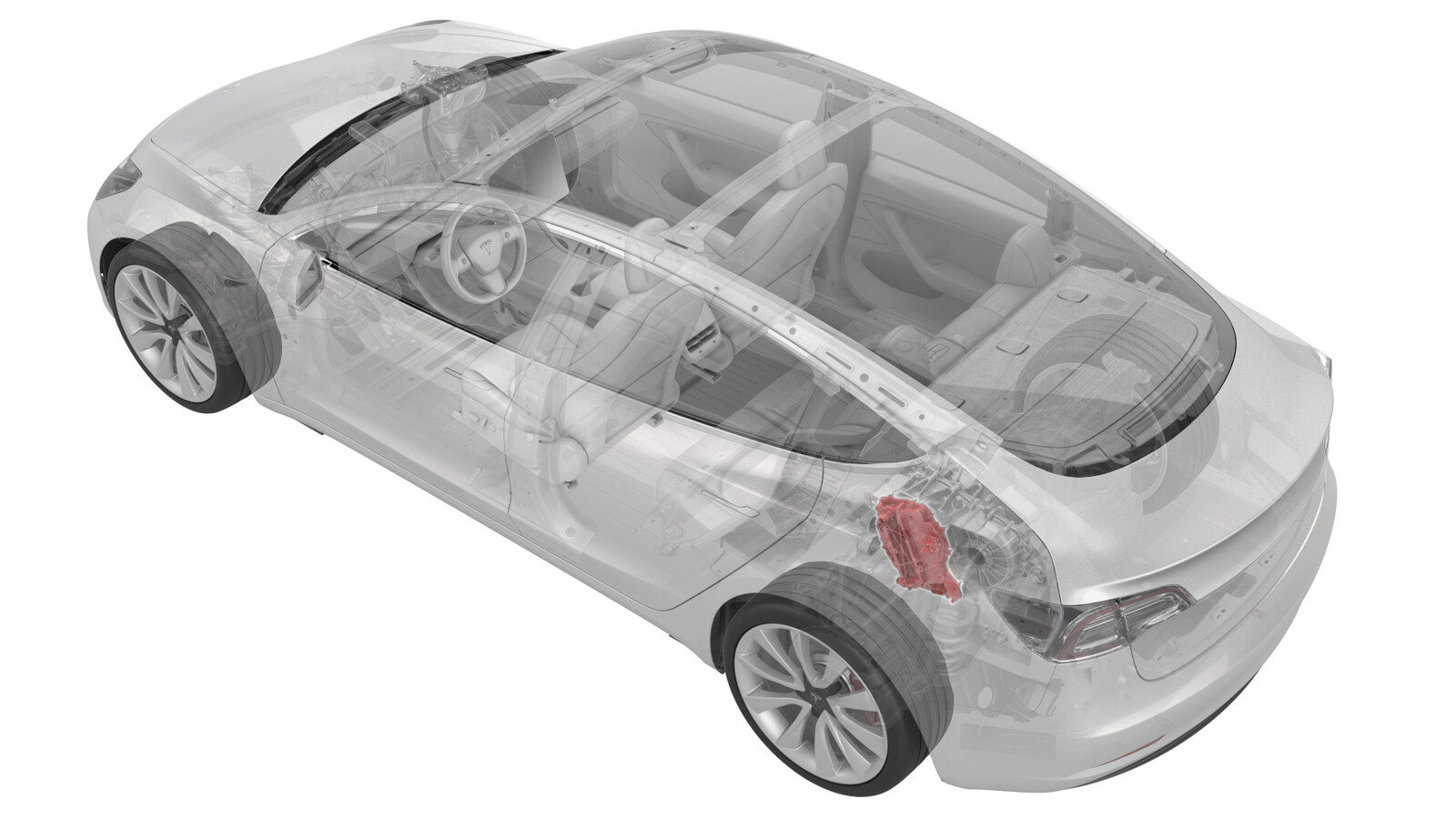
Inverter Air Leak Test
 Correction code
40202020
0.10
NOTE: Unless otherwise explicitly
stated in the procedure, the above correction code and FRT reflect all of the work
required to perform this procedure, including the linked procedures. Do not stack correction codes unless
explicitly told to do so.
NOTE: See Flat Rate
Times to learn more about FRTs and how they are created. To provide feedback on
FRT values, email ServiceManualFeedback@tesla.com.
NOTE: See Personal Protection to make sure wearing proper PPE when
performing the below procedure. See Ergonomic Precautions for safe and healthy working practices.
- 2023-05-18: Updated tools list and added photos for 4DU adapter and plug.
- 1450875-00-A Kit, Inverter Leak Test Adapter, M3
- 1026636-00-A Pack Enclosure Leak Tester, HV Battery
- 1140311-00-A Lever Lock, HV Connector, Model 3
- 1880705-00-A 4DU Inverter Leak Test Plug Assembly
- 1942298-00-A 4DU Inverter Leak Test Adapter
Procedure
- Perform the vehicle electrical isolation procedure. See Vehicle HV Disablement Procedure.
- Remove the mid aero shield panel. See Panel - Aero Shield - Rear (Remove and Replace).
-
Disconnect the electrical
harness from the inverter logic connector.
-
Install the logic connector dummy plug into the logic connector.
Figure 1. 3DU Figure 2. 4DU -
Slide the release to unlock
the rear drive unit HV connector handle of the rear drive unit to HV battery
harness from the secured position.
-
Fully raise the handle on
the rear drive unit HV connector.
- Remove the rear drive unit HV connector from the rear drive unit HV header.
-
Install the leak test
adapter into the rear drive unit HV header.
Figure 3. 3DU Figure 4. 4DU -
Connect the pack enclosure
leak tester to the leak test adapter on the rear drive unit HV header.
- Close both valves on the pack enclosure leak tester, and then connect a compressed air supply line.
- Fully close the regulator, and then open the inlet valve.
- Set the regulator to 1 psi.
- Open the outlet valve, and allow at least 45 seconds for the pressure to stabilize to 1 psi.
- Close the inlet valve, record the starting pressure displayed, and then start a 60-second timer.
- After 60 seconds record the ending pressure displayed.
-
Subtract the ending pressure
from the starting pressure: the acceptable pressure difference is 0.2 psi or
less.
- If the difference is 0.2 psi or less, continue the procedure.
- If the difference is more than 0.2 psi, check the hose, adapter, and plug fittings, close the outlet valve and open the inlet valve, check the regulator pressure, and then retest from step 13. If the difference is still more than 0.2 psi, refer to Toolbox article 6415200 (Tesla Internal) or 6415200 (External parties).
- Disconnect the air supply from the pack enclosure leak tester.
-
Open the inlet valve, and
then disconnect the pack enclosure leak tester from the leak test adapter on
the rear drive unit HV header.
-
Remove the leak test adapter
from the rear drive unit HV header.
Figure 5. 3DU Figure 6. 4DU -
Fully raise the handle on
the rear drive unit HV connector of the rear drive unit to HV battery
harness.
-
Install the HV connector
special tool onto the rear drive unit HV connector.
-
Use both hands to firmly
connect the rear drive unit HV connector of the rear drive unit to HV
battery harness to the rear drive unit HV header.
CAUTIONMake sure that the connector fits the header squarely and tightly, and that both retention pins enter the handle.
- Remove the HV connector special tool from the rear drive unit HV connector.
-
While pressing the rear
drive unit HV connector onto the rear drive unit HV header, fully lower the
handle.
CAUTIONMake sure that the handle does not bind as it is lowered.
-
Slide the release to lock
the rear drive unit HV connector handle in the secured position.
-
Verfiy that the rear drive
unit HV connector is fully seated, and compare both sides of the connector
that it is properly secured in place.
NoteAn improperly seated connector might lead to connector damage and rear drive unit problems later on.
-
Remove the logic connector
dummy plug from the logic connector.
Figure 7. 3DU Figure 8. 4DU -
Connect the electrical harness to the inverter logic connector.
- Install the mid aero shield panel. See Panel - Aero Shield - Rear (Remove and Replace).
- Connect 12V power. See 12V/LV Power (Disconnect and Connect).