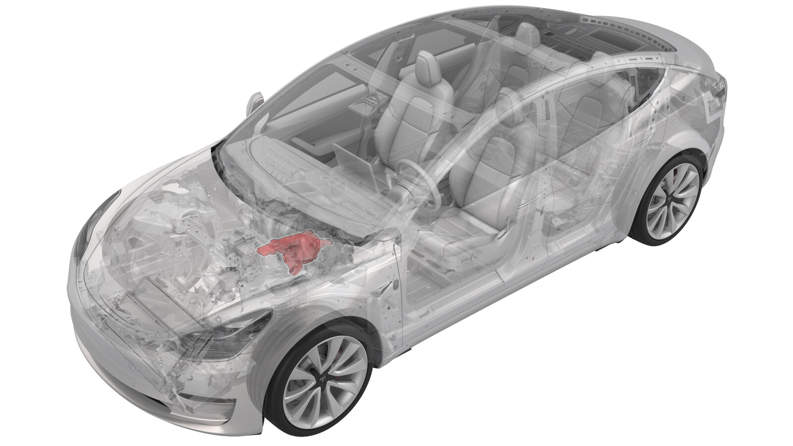
Booster - Brake - Electromechanical (Heat Pump) (LHD) (Remove and Replace)
 Correction code
33201202
1.95
NOTE: Unless otherwise explicitly
stated in the procedure, the above correction code and FRT reflect all of the work
required to perform this procedure, including the linked procedures. Do not stack correction codes unless
explicitly told to do so.
NOTE: See Flat Rate
Times to learn more about FRTs and how they are created.
NOTE: See Personal Protection to make sure wearing proper PPE when
performing the below procedure. NOTE: See Ergonomic Precautions for safe and healthy working
practices.
Correction code
33201202
1.95
NOTE: Unless otherwise explicitly
stated in the procedure, the above correction code and FRT reflect all of the work
required to perform this procedure, including the linked procedures. Do not stack correction codes unless
explicitly told to do so.
NOTE: See Flat Rate
Times to learn more about FRTs and how they are created.
NOTE: See Personal Protection to make sure wearing proper PPE when
performing the below procedure. NOTE: See Ergonomic Precautions for safe and healthy working
practices.
Equipment:
- 1079041-00-A Flare nut crowfoot set
- 1134520-00-A Kit, EPB Release, Handheld
- 1129348-00-A XP-10 Power Supply, XP-10
Remove
-
CAUTION
Brake fluid dissolves paint. Have clean towels and plenty of water standing by to wash spilled brake fluid off painted surfaces.
NoteDispose of used brake fluid in a manner consistent with local environmental codes.
- Open all four doors.
- Lower all four windows.
- Move LH front seat backward.
- Remove the rear underhood apron. See Underhood Apron - Rear (Remove and Replace).
- Remove the cabin intake duct. See Duct - Upper - Cabin Intake (Remove and Replace).
- Remove the underhood storage unit. See Underhood Storage Unit (Remove and Replace).
- Remove the LH and RH wiper arms. See Wiper Arms (Remove and Replace).
- Remove the LH and RH shock tower covers. See Cover - Shock Tower - LH (Remove and Replace).
- Remove the cowl screen panel. See Panel - Cowl Screen (Remove and Replace).
- Disconnect 12V power. See 12V/LV Power (Disconnect and Connect).
- Remove the 12V auxiliary battery. See 12V/LV Battery (Remove and Replace).
- Remove the front body controller module. See Module - Body Controller - Front (Heat Pump) (Remove and Replace)
- Remove the wiper motor. See Wiper Module (Remove and Replace).
-
Disconnect the electrical
harness from the brake fluid reservoir connector.
-
Disconnect the harness
connectors (x2) from the brake booster assembly.
- Place absorbent material under the reservoir and booster.
- Using a brake fluid syringe, remove fluid from the reservoir.
-
Loosen the nuts that attach
the brake lines to the booster, and then slide the nuts back on the brake
lines.
 16 Nm (11.8 lbs-ft)
 - Remove the driver footwell cover. See Cover - Footwell - Driver (Remove and Replace).
- Remove the driver knee airbag. See Airbag - Knee - Driver (Remove and Install).
-
Remove the brake switch. See
Switch - Brake Light (Remove and Replace).
CAUTIONReplace the brake switch if damaged during removal.
-
Remove the cotter clip from
the clevis pin on the brake pedal assembly.
-
Remove the clevis pin from the brake pedal assembly.
-
Remove and discard the nuts
(x4) that attach the brake booster to the bulkhead.
 16.5 Nm (12.2 lbs-ft)
 -
Remove the LH bolt securing front harness bracket from the vehicle.
 9 Nm (6.6 lbs-ft)NoteMake sure the harness bracket is able to move in a wide range, and the bracket and ibooster are not obstructed.
 -
Remove the brake booster
assembly from the vehicle.
CAUTIONHandle the electromechanical brake booster only by the main housing. Do not use the pushrod, the reservoir, or the connectors to lift or manipulate the electromechanical brake booster.
Install
-
Position the brake booster
on the vehicle, and then install the new nuts (x4) that attach the booster
to the bulkhead.16.5 Nm (12.2 lbs-ft)CAUTIONHandle the electromechanical brake booster only by the main housing. Do not use the pushrod, the reservoir, or the connectors to lift or manipulate the electromechanical brake booster.
-
Align the brake pedal with
the brake booster rod, and then install the clevis pin to the brake pedal
assembly.
-
Install the cotter clip to
the clevis pin on the brake pedal assembly.
- Install the brake switch. See Switch - Brake Light (Remove and Replace).
- Install the driver knee airbag. See Airbag - Knee - Driver (Remove and Install).
- Install the driver footwell cover. See Cover - Footwell - Driver (Remove and Replace).
-
Install the nuts that attach
the brake lines to the booster.16 Nm (11.8 lbs-ft)
- Clean the area around the brake fluid reservioir and then remove the cap.
-
Fill the brake fluid reservoir to the "MAX" level.
CAUTIONMake sure not to get any brake fluid on any painted surface. Clean residual brake fluid with a shop towel.
- Remove the absorbent material from underneath the brake booster and reservoir area.
- Connect the electrical harness connectors (x2) to the electromechanical brake booster connector.
-
Connect the electrical
harness to the brake fluid reservoir connector.
-
Install the LH bolt securing
the front harness bracket of the vehicle.9 Nm (6.6 lbs-ft)
- Install the wiper motor. See Wiper Module (Remove and Replace).
- Install the front body controller module. See Module - Body Controller - Front (Heat Pump) (Remove and Replace).
- Install the 12V Battery. See 12V/LV Battery (Remove and Replace).
- Install the cowl screen panel. See Panel - Cowl Screen (Remove and Replace).
- Install the LH and RH shock tower covers. See Cover - Shock Tower - LH (Remove and Replace).
- Install the LH and RH wiper arms. See Wiper Arms (Remove and Replace).
- Install the underhood storage unit. See Underhood Storage Unit (Remove and Replace).
- Install the cabin intake duct. See Duct - Upper - Cabin Intake (Remove and Replace).
- Reconnect 12V power. See 12V/LV Power (Disconnect and Connect).
- Reinstall the vehicle firmware. See Software Reinstall - Touchscreen.
- Bleed the braking system. See Brake Fluid Bleed/Flush.
- Install the cabin intake duct. See Duct - Upper - Cabin Intake (Remove and Replace).
- Install the rear underhood apron. See Underhood Apron - Rear (Remove and Replace).
- Open all four doors.
- Move LH front seat to original position.
- Raise all windows.
- Remove lift arms from below vehicle.
- Close all four doors.
- Perform a road test using a series of panic stops to make sure there is proper pedal feel and brake performance.