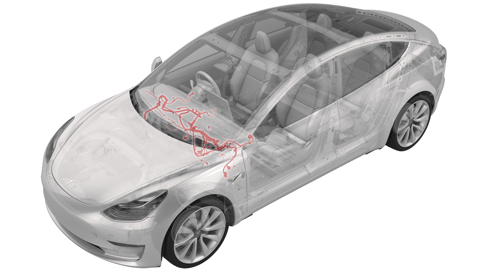
Harness - Instrument Panel (RHD) (Remove and Replace)
 Correction code
17100622
2.70
NOTE: Unless otherwise explicitly
stated in the procedure, the above correction code and FRT reflect all of the work
required to perform this procedure, including the linked procedures. Do not stack correction codes unless
explicitly told to do so.
NOTE: See Flat Rate
Times to learn more about FRTs and how they are created.
NOTE: See Personal Protection to make sure wearing proper PPE when
performing the below procedure. NOTE: See Ergonomic Precautions for safe and healthy working
practices.
Correction code
17100622
2.70
NOTE: Unless otherwise explicitly
stated in the procedure, the above correction code and FRT reflect all of the work
required to perform this procedure, including the linked procedures. Do not stack correction codes unless
explicitly told to do so.
NOTE: See Flat Rate
Times to learn more about FRTs and how they are created.
NOTE: See Personal Protection to make sure wearing proper PPE when
performing the below procedure. NOTE: See Ergonomic Precautions for safe and healthy working
practices.
Remove
- Open all doors, and latch the rear doors to prevent accidental closing.
- Lower all windows.
- Set the steering wheel straight ahead.
- Remove the rear underhood apron. See Underhood Apron - Rear (Remove and Replace).
- Remove the LH and RH lower A-pillar trim. See Trim - A-Pillar - Lower - LH (Remove and Replace).
- Remove the LH and RH middle A-pillar trim. See Trim - A-Pillar - Middle - LH (Remove and Replace).
- Remove the LH footwell cover. See Cover - Footwell - Passenger (RHD) (Remove and Replace).
- Remove the RH footwell vent duct. See Duct - Footwell - RH (RHD) (Remove and Replace).
- Open the glove box.
- Disconnect 12V power. See 12V/LV Power (Disconnect and Connect).
- Remove the LH and RH front seats. See Seat Assembly - 1st Row - LH (Remove and Replace).
- Remove the center console. See Center Console (Remove and Replace).
- Remove the main instrument panel décor trim. See Decor Trim - Instrument Panel - Main (Remove and Replace).
- Remove the glove box. See Glove Box - Without Knee Airbags (Remove and Replace).
-
Remove the clips (x3) that
attach the LH air wave duct.
- Remove the steering wheel. See Steering Wheel (Remove and Install).
- Remove the steering column control module. See Module - Steering Column Control (Remove and Replace).
-
Release the clips (x4) that
attach the instrument panel service panel to the instrument panel, and then
disconnect temperature sensor connector.
- Remove the touchscreen and the center display housing. See Touchscreen (Remove and Replace).
- Remove the vent finisher. See Finisher - Vent (Remove and Replace).
- Remove the screw (torque 2.3 Nm) that attaches the RH air duct to the instrument panel, and then release the air duct from the instrument panel.
-
Disconnect the harness
connector from the RH air duct and remove the duct.
- Remove the screw (torque 2.3 Nm) that attaches the LH air duct to the instrument panel, and then release the air duct from the instrument panel.
-
Disconnect the harness connector from the LH air duct and remove the
duct.
- Remove the speaker grille. See Grille - Speaker - Instrument Panel (Remove and Replace).
- Remove the LH and RH dash speakers. See Speaker - Dash - LH (Remove and Replace).
- Remove the center dash speaker. See Speaker - Dash - Center (Remove and Replace).
- Remove the dash tweeter. See Tweeter - Dash (Remove and Replace).
-
Disconnect the electrical
wiring harness from the front passenger airbag connectors (x3).
-
Remove and discard the bolts
(x4) that attach the front passenger airbag to the cross car beam.
 8 Nm (5.9 lbs-ft)
 -
Remove the screws (x2) that
attach the IP carrier to the cross car beam near the front passenger airbag
(torque 2.3 Nm).
-
Remove the screws (x11) that
attach the IP carrier to the cross car beam.
 2.3 Nm (1.7 lbs-ft)
Figure 1. LHD shown, RHD similar - Slightly release the instrument panel carrier from the cross car beam to gain access to the E-call antenna. See IP Carrier (Remove and Install).
-
Disconnect the harness
connector from the E-call antenna.
-
Remove the instrument panel carrier from the cross car beam.
CAUTIONMake sure to clear the harness attached to the top of the HVAC assembly.
- Remove the screws (x2) that attach the RH air wave duct to the cross car beam (torque 2.3 Nm) and then remove the RH air wave duct fro the HVAC assembly.
- Remove the the LH and RH front main carpets.
-
Disconnect the headliner
electrical harness.
-
Release the clips that
attach the headliner electrical harness and move it aside.
LHD shown, RHD similar
-
Disconnect the instrument
panel harness connectors from the LH body controller module, and then remove
the harness clip from the instrument panel near the LH body
controller.
Note1x connector J6 (Dash), 1x connector J9 (HVAC), 2x coax connectors.
LHD shown, RHD similar
-
Disconnect the instrument
panel harness connector from the electronic steering column.
-
Release the clips that
attach the electrical harness to the steering column.
-
Disconnect the instrument
panel electrical harness connector from the HVAC fan motor, and then release
the blower motor harness clips (x2) from the cross car beam.
-
Disconnect the instrument
panel harness connector from the PTC heater.
-
Release the clip that
attaches the instrument panel electrical harness to the PTC heater.
- Remove the instrument panel harness clips (x3) from the top of the cross car beam and release the HVAC harness from the instrument panel harness.
-
Release the clips that
attaches the instrument panel electrical harness to the RH side of the HVAC
assembly.
-
Remove the nut (torque 5 Nm)
that attaches the instrument panel harness ground strap to the PTC heater,
and then put the ground strap aside.
-
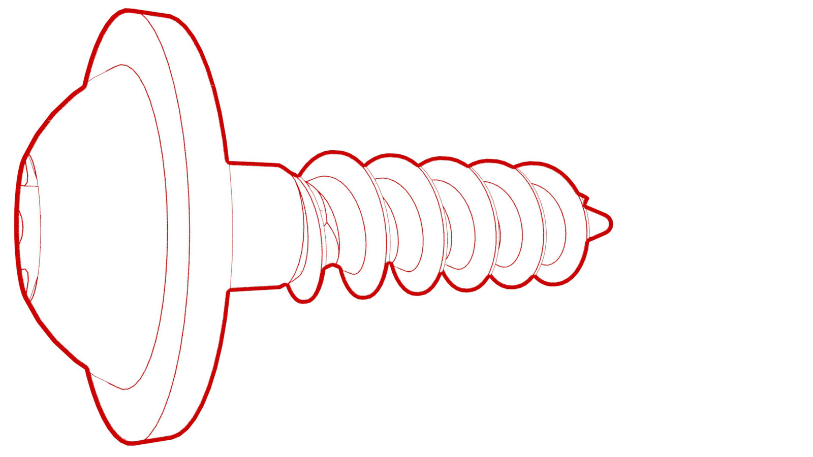
Remove and discard the bolt
(torque 8 Nm) that attaches the instrument panel electrical harness ground
strap to the body near the RCM.
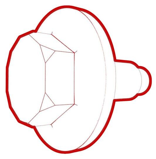
Figure 2. LHD shown, RHD similar -
Disconnect the instrument
panel electrical harness connector from the RCM.
Figure 3. LHD shown, RHD similar -
Release the clips that
attach the instrument panel electrical harness to the body.
- Release the instrument panel harness clips (x3) on the LH side of the instrument panel.
-
Disconnect the instrument
panel electrical harness from the car computer connectors.
NoteVehicles with E-call system have 4 connectors, vehicles without E-call system have 3 connectors.
- Release the center speaker harness from the HVAC case.
-
Disconnect the instrument
panel electrical harness from the RH body controller module
connectors.
Figure 4. LHD shown, RHD models have 2 connectors -
Disconnect the 3 inline
electrical connectors at the RH lower A-pillar area.
-
Release the quad cam harness
clip from the cross car beam.
-
Release the HVAC harness
clips (x3) from the instrument panel harness.
-
Remove the fasteners that
attach the RH cross car beam bracket, and then remove the bracket from the
vehicle.
 25 Nm (18.4 lbs-ft)
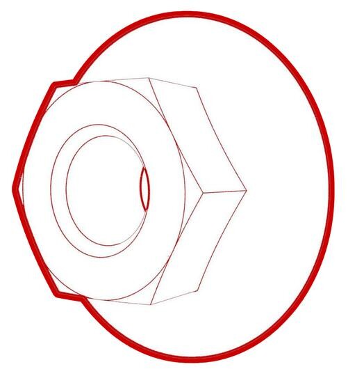 25 Nm (18.4 lbs-ft)
 - Remove the instrument panel harness from center console area and move it aside.
-
Remove the instrument panel
harness from the cross car beam.
NoteRemember the instrument panel harness routing for installation
Install
Installation procedure is the reverse of removal.