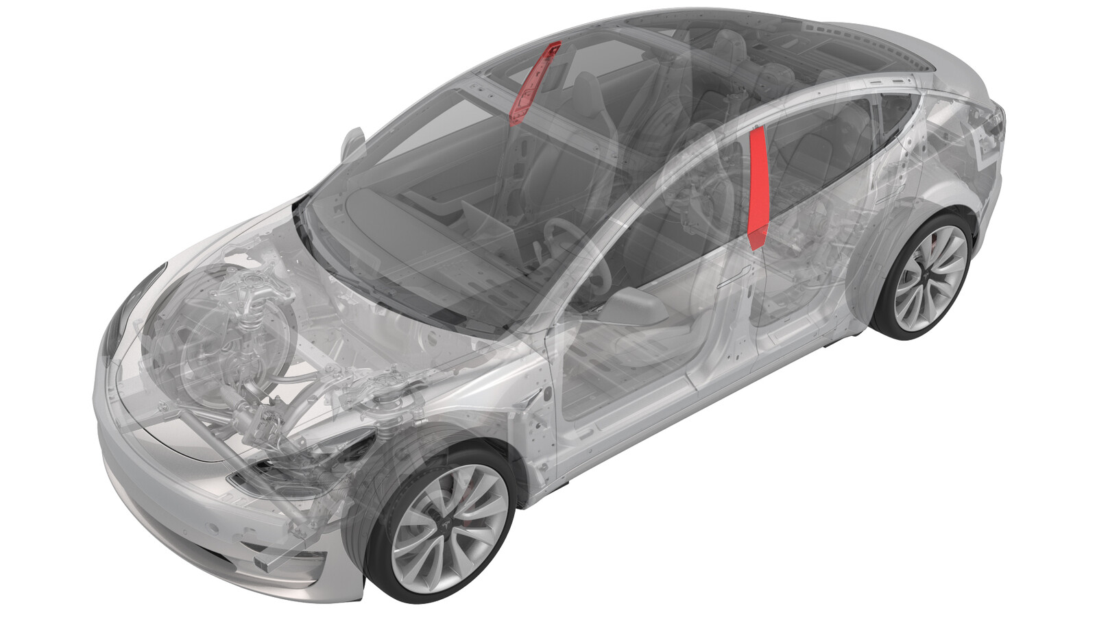
Applique - B-Pillar - LH (Remove and Replace)
 Correction code
12200102
0.18
NOTE: Unless otherwise explicitly
stated in the procedure, the above correction code and FRT reflect all of the work
required to perform this procedure, including the linked procedures. Do not stack correction codes unless
explicitly told to do so.
NOTE: See Flat Rate
Times to learn more about FRTs and how they are created.
NOTE: See Personal Protection to make sure wearing proper PPE when
performing the below procedure. NOTE: See Ergonomic Precautions for safe and healthy working
practices.
Correction code
12200102
0.18
NOTE: Unless otherwise explicitly
stated in the procedure, the above correction code and FRT reflect all of the work
required to perform this procedure, including the linked procedures. Do not stack correction codes unless
explicitly told to do so.
NOTE: See Flat Rate
Times to learn more about FRTs and how they are created.
NOTE: See Personal Protection to make sure wearing proper PPE when
performing the below procedure. NOTE: See Ergonomic Precautions for safe and healthy working
practices.
- 2026-01-19: Added the step of releasing/installing the lower part of the B-pillar applique, and updated the way of performing the routine.
- LH B-Pillar Applique - Replaces the LH side-view DAS camera, the external NFC key card reader, and the LH Bluetooth endpoint.
- RH B-Pillar Applique - Replaces the RH side-view DAS camera and the RH Bluetooth endpoint.
Torque Specifications
| Description | Torque Value | Recommended Tools | Reuse/Replace | Notes |
|---|---|---|---|---|
| Bolts (x2) that attach the B-pillar applique to the body |
 5 Nm (3.7 lbs-ft) |
|
Reuse | Some vehicles are equipped with 8mm bolts, some are equipped with T25 bolts. |
Remove
- Open the LH front and rear doors and lower the LH front and rear windows.
-
Release the clips that attach the B-pillar applique fastener cover to the vehicle, and then remove the cover.
-
Remove the bolts (x2) that
attach the B-pillar applique to the body, but do not remove the applique
from the vehicle at this time.
NoteSome vehicles are equipped with 8mm bolts, some are equipped with T25 bolts.TIpUse of the following tool(s) is recommended:
- 8 mm socket
- Torx T25 socket
-
Pry outward to release the lower part of the LH B-pillar applique.
CAUTIONTake care not to apply excessive force to avoid damage.
-
Release the B-pillar applique from the
body, and then disconnect the
camera connectors from the B-pillar applique.
CAUTIONUse caution not to damage the camera connectors.
-
Remove the B-pillar applique from the
vehicle.
Install
-
Connect the camera connectors to the B-pillar applique, and then position the applique onto the vehicle.
- Install the lower part of the LH B-pillar applique.
-
Install the bolts (x2) that
attach the B-pillar applique to the body.5 Nm (3.7 lbs-ft)TIpUse of the following tool(s) is recommended:
- 8 mm socket
- Torx T25 socket
-
Position the B-pillar
applique fastener cover onto the
vehicle, and then engage the clips that attach the B-pillar applique fastener cover to the vehicle.
- Close the LH rear door.
- Remove the protective film from the B-pillar assembly.
-
Reinstall the vehicle firmware. See
Software Reinstall - Touchscreen.
NoteSkip this step if reinstalling the original B-pillar applique assembly that came with the vehicle.
- On the touchscreen, tap the Service Mode "wrench" (at the bottom of the touchscreen UI), and then tap , select BPillars from the drop list, click Run, and allow the routine to complete.
- Exit Service Mode. See Service Mode.
- Verify that all key cards work on the B-pillar applique as designed.
-
Inform the customer that manual driving is now required to allow the camera to self-calibrate.
NoteSelf-calibration can take up to 100 miles (160 km) of manual driving, depending upon the road type and condition. Until self-calibration is complete, the message "Autopilot Features Currently Unavailable: Manual Driving Required While Camera Is Calibrating" is displayed if an attempt is made to engage an Autopilot feature.