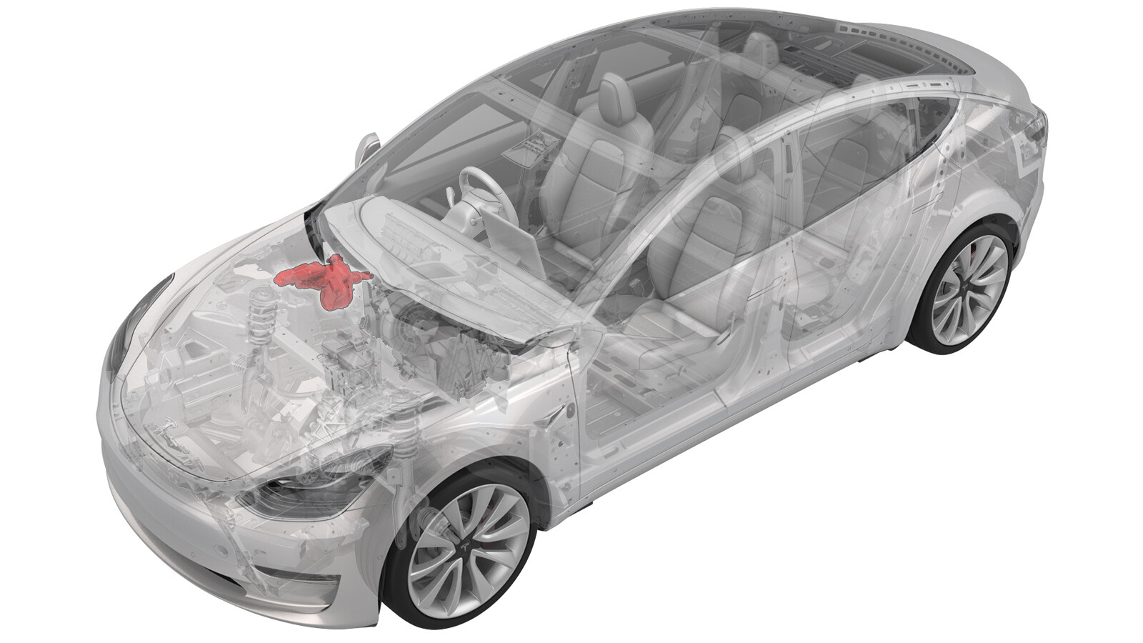
Electromechanical Brake Booster Assembly (Non-Heat Pump) (RHD) (Remove and Replace)
 Correction code
33201102
1.62
NOTE: Unless otherwise explicitly
stated in the procedure, the above correction code and FRT reflect all of the work
required to perform this procedure, including the linked procedures. Do not stack correction codes unless
explicitly told to do so.
NOTE: See Flat Rate
Times to learn more about FRTs and how they are created.
NOTE: See Personal Protection to make sure wearing proper PPE when
performing the below procedure. NOTE: See Ergonomic Precautions for safe and healthy working
practices.
Correction code
33201102
1.62
NOTE: Unless otherwise explicitly
stated in the procedure, the above correction code and FRT reflect all of the work
required to perform this procedure, including the linked procedures. Do not stack correction codes unless
explicitly told to do so.
NOTE: See Flat Rate
Times to learn more about FRTs and how they are created.
NOTE: See Personal Protection to make sure wearing proper PPE when
performing the below procedure. NOTE: See Ergonomic Precautions for safe and healthy working
practices.
- 2025-07-07: Added step to bleed the brakes through the inner bleed valves only.
Equipment:
- 1079041-00-A Flare nut crowfoot set
- 1134520-00-A Kit, EPB Release, Handheld
- 1129348-00-A XP-10 Power Supply, XP-10
Remove
-
CAUTION
Brake fluid dissolves paint. Have clean towels and plenty of water standing by to wash spilled brake fluid off painted surfaces.
NoteDispose of used brake fluid in a manner consistent with local environmental codes.
- Remove the rear underhood apron. See Underhood Apron - Rear (Remove and Replace).
- Remove the cabin intake duct. See Duct - Upper - Cabin Intake (Remove and Replace).
- Remove the underhood storage unit. See Underhood Storage Unit (Remove and Replace).
- Remove the LH and RH wiper arms. See Wiper Arms (Remove and Replace).
- Remove the LH and RH shock tower covers. See Cover - Shock Tower - LH (Remove and Replace).
- Remove the cowl screen panel. See Panel - Cowl Screen (Remove and Replace).
- Remove the wiper motor. See Wiper Module (Remove and Replace).
- Remove the HVAC plenum outer duct. See Plenum - Inlet - HVAC (Remove and Replace).
- Remove the HVAC plenum inner duct. See Duct - HVAC Plenum - Inner (Remove and Replace).
- Disconnect 12V power. See 12V/LV Power (Disconnect and Connect).
-
Disconnect the electrical harness from the brake fluid reservoir connector.
Figure 1. Left-Hand Drive (LHD) shown, Right-Hand Drive (RHD) similar - Disconnect the electrical harness connectors (x2) from the electromechanical brake booster connector.
- Place absorbent material under the reservoir and booster.
- Remove brake fluid from the reservoir.
-
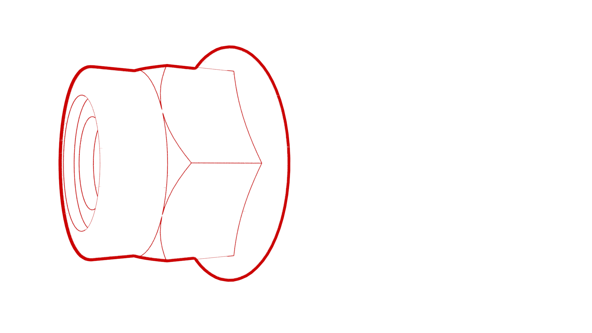
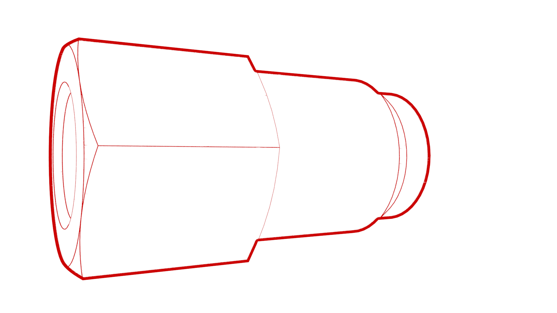
Loosen the nuts that attach the brake lines to the booster, and then slide the nuts back on the brake lines.
Figure 2. LHD shown, RHD similar - Remove the driver footwell cover. See Cover - Footwell - Driver (Remove and Replace).
-
Release the clip (x1) that
attaches the driver knee airbag cover to the air duct, release the clips
(x5) that attach the driver knee airbag cover to the vehicle, and then
remove the cover.
- Remove the brake switch. See Switch - Brake Light (Remove and Replace).
-
Release the brake clevis clip from the clevis pin.
Figure 3. LHD shown, RHD similar -
Remove the clevis pin from the brake pedal assembly.
Figure 4. LHD shown, RHD similar -
Remove and discard the nuts
(x4) that attach the brake booster to the bulkhead, and then remove the
brake booster from the vehicle.
CAUTIONHandle the electromechanical brake booster only by the main housing. Do not use the pushrod, the reservoir, or the connectors to lift or manipulate the electromechanical brake booster.
Figure 5. LHD shown, RHD similar Figure 6. LHD shown, RHD similar
Install
-
Position the brake booster
on the vehicle, and then install the new nuts (x4) that attach the booster
to the bulkhead.
 16.5 Nm (12.2 lbs-ft)CAUTIONHandle the electromechanical brake booster only by the main housing. Do not use the pushrod, the reservoir, or the connectors to lift or manipulate the electromechanical brake booster.
Figure 7. LHD shown, RHD similar -
Align the brake pedal with the brake booster rod, and then install the clevis pin on the brake pedal assembly.
Figure 8. LHD shown, RHD similar -
Install the brake clevis clip on the clevis pin.
Figure 9. LHD shown, RHD similar - Install the brake switch. See Switch - Brake Light (Remove and Replace).
-
Position the driver knee airbag cover on the vehicle, and then install the clips (x4) that attach the driver knee airbag cover to the vehicle.
-
Install the clip that attaches the driver knee airbag cover to the air duct.
- Install the driver footwell cover. See Cover - Footwell - Driver (Remove and Replace).
-
Install the nuts that attach the brake lines to the booster.
 16 Nm (11.8 lbs-ft)
Figure 10. LHD shown, RHD similar - Clean the area around the brake fluid reservioir and cap, and then fill the reservoir.
- Remove the absorbent material from under the brake fluid reservoir.
- Connect the electrical harness connectors (x2) to the electromechanical brake booster connector.
-
Connect the electrical harness to the brake fluid reservoir connector.
Figure 11. LHD shown, RHD similar - Install the HVAC plenum inner duct. See Duct - HVAC Plenum - Inner (Remove and Replace).
- Install the HVAC plenum outer duct. See Plenum - Inlet - HVAC (Remove and Replace).
- Install the wiper motor. See Wiper Module (Remove and Replace).
- Install the cowl screen panel. See Panel - Cowl Screen (Remove and Replace).
- Install the LH and RH shock tower covers. See Cover - Shock Tower - LH (Remove and Replace).
- Install the LH and RH wiper arms. See Wiper Arms (Remove and Replace).
- Install the underhood storage unit. See Underhood Storage Unit (Remove and Replace).
- Reconnect 12V power. See 12V/LV Power (Disconnect and Connect).
- Reinstall the vehicle firmware. See Software Reinstall - Touchscreen.
-
Bleed the LH and RH front brake
calipers through the brake calipers' inner bleed valves until clean fluid without air bubbles flows out of the
caliper.
NoteIt is not necessary to bleed the brake calipers through the outer bleed valves.
- Flush the LH front caliper using the inner bleed valve until a noticeable reduction in air bubbles is observed.
- Flush the RH front caliper using the inner bleed valve until a noticeable reduction in air bubbles is observed.
- Bleed the LH front caliper using the inner bleed valve. See Brake Fluid Bleed/Flush for details.
- Bleed the RH front caliper using the inner bleed valve. See Brake Fluid Bleed/Flush for details.
- Make sure to perform the brake stiffness test. See Brake Fluid Bleed/Flush for details.
- Install the cabin intake duct. See Duct - Upper - Cabin Intake (Remove and Replace).
- Install the rear underhood apron. See Underhood Apron - Rear (Remove and Replace).