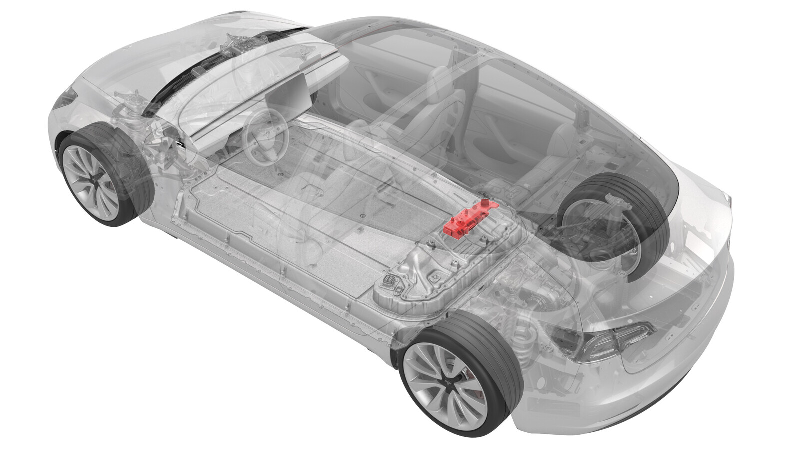
Controller - High Voltage (Remove and Replace)
 Correction code
16301602
1.32
NOTE: Unless otherwise explicitly
stated in the procedure, the above correction code and FRT reflect all of the work
required to perform this procedure, including the linked procedures. Do not stack correction codes unless
explicitly told to do so.
NOTE: See Flat Rate
Times to learn more about FRTs and how they are created.
NOTE: See Personal Protection to make sure wearing proper PPE when
performing the below procedure. NOTE: See Ergonomic Precautions for safe and healthy working
practices.
Correction code
16301602
1.32
NOTE: Unless otherwise explicitly
stated in the procedure, the above correction code and FRT reflect all of the work
required to perform this procedure, including the linked procedures. Do not stack correction codes unless
explicitly told to do so.
NOTE: See Flat Rate
Times to learn more about FRTs and how they are created.
NOTE: See Personal Protection to make sure wearing proper PPE when
performing the below procedure. NOTE: See Ergonomic Precautions for safe and healthy working
practices.
- 2026-05-07: Added ancillary bay cover aluminum tape part number for clarity purposes.
- 2025-11-14: Added step to apply dielectric grease to the X484 connector. Added step to tuck the pyrotechnic disconnect harness underneath the ancillary bay harness.
- 2025-11-11: Added step to check high voltage controller part number and retrofit high voltage controller hinge tray, if required.
Only
technicians who have completed all required certification courses are permitted to
perform this procedure. Tesla recommends third party service provider technicians
undergo equivalent training before performing this procedure. For more information on
Tesla Technician requirements, or descriptions of the subject matter for third parties,
see HV Certification Requirements. Proper personal protective equipment (PPE) and insulating HV
gloves with a minimum rating of class 0 (1000V) must
be worn at all times a high voltage cable, busbar, or fitting is handled. Refer to Tech Note TN-15-92-003, High Voltage Awareness
Care Points
for additional safety
information.
- 3M 425 Aluminum Shielding Foil Tape, Acrylic, 4.60 mil Thick, 2" X 5 yd., Silver - 0601363
- NYE Rheotemp 768G Grease or Super Lube Dielectric Grease
Remove
- If the high voltage controller is being removed as part of another component's replacement procedure, and the same controller will be installed later, go to step 3. Otherwise, continue to the next step.
- Perform a backup of the high voltage controller data. See Controller - High Voltage (Backup and Restore).
- Remove the rear underhood apron. See Underhood Apron - Rear (Remove and Replace).
- Disconnect 12V/LV power. See 12V/LV Power (Disconnect and Connect).
- Perform the vehicle isolation procedure. See Vehicle HV Disablement Procedure.
- Remove the 2nd row seat cushion. See Seat Cushion - Lower - 2nd Row (Remove and Replace).
- Remove the ancillary bay cover. See Cover - Ancillary Bay (Remove and Install).
- Remove the pyrotechnic battery disconnect. See Pyrotechnic Battery Disconnect (Remove and Replace).
-
Disconnect the ancillary bay harness from the high voltage controller connectors.
-
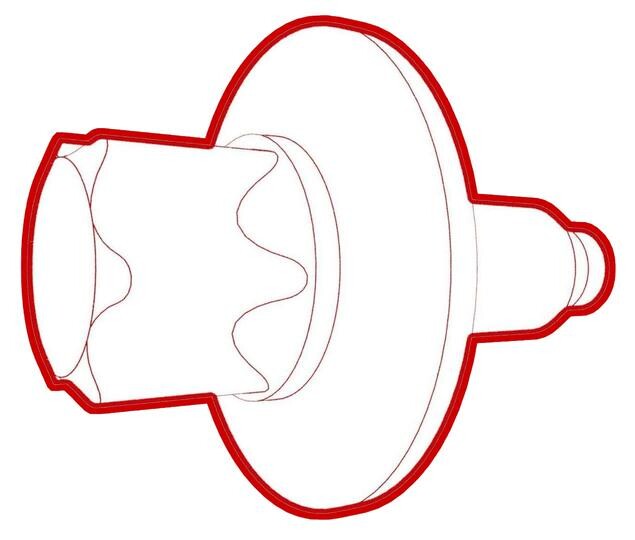
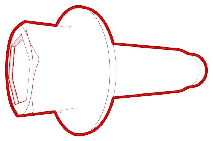
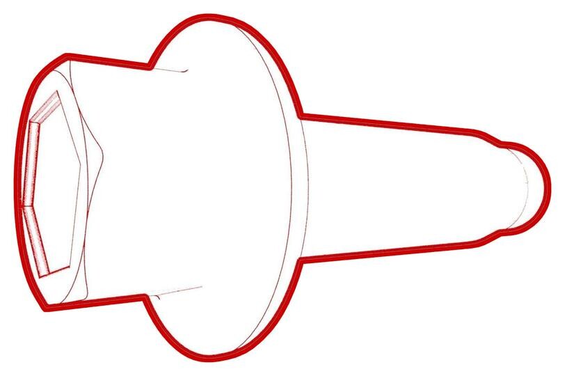
Remove the bolts that attach the high voltage controller to the hinge tray, and then remove the controller from the vehicle.
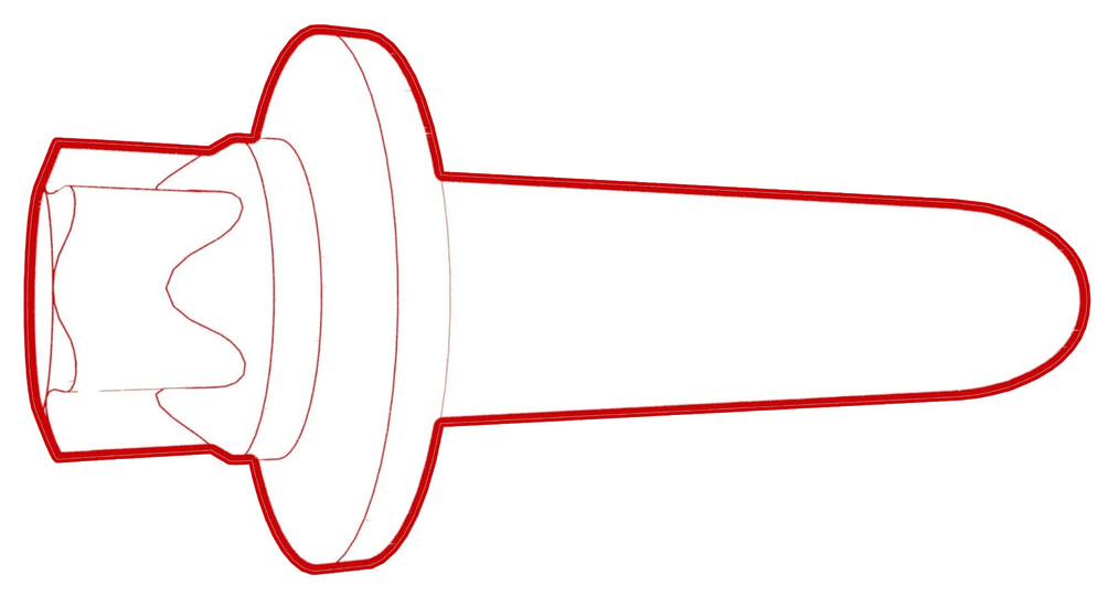 2 Nm (1.5 lbs-ft)
Figure 1. 5-Bolt High Voltage Controller Figure 2. 4-Bolt High Voltage Controller Figure 3. 3-Bolt High Voltage Controller
Install
- Inspect the new high voltage controller. When replacing from -E, -F, -G, -H, -0x-L, -1x-L or -2x-L to xx-N or -xx-P, the high voltage controller hinge tray must be retrofitted. See Hinge Tray - High Voltage Controller(Retrofit) and add the correction code as a separate activity to the Service Visit.
-
Install the high voltage controller into the ancillary bay, and then install the bolts that attach the high voltage controller to the hinge tray.2 Nm (1.5 lbs-ft)
-
Apply dielectric grease to the X484 connector cavity.
CAUTIONUse a syringe if possible and do not bend the connector pins.
Figure 4. X484 Connector -
Connect the ancillary bay harness to the high voltage controller connectors.
NoteWipe off any excess grease after inserting the X484 connector.
-
Install the pyrotechnic battery disconnect. See Pyrotechnic Battery Disconnect (Remove and Replace).
NoteDo not install the ancillary bay cover at this time.
-
Tuck the pyrotechnic disconnect wiring under the main ancillary bay harness.
- If the high voltage controller was removed and then installed as part of another component's replacement procedure, return to that procedure.
- Use IPA wipes to clean the ancillary bay cover gasket surface, and the mating surface of the HV battery.
-
Visually inspect the condition of the ancillary bay cover gasket and the HV battery mating surface for cracks, cuts, gouges, abrasions, or any damage that could affect the seal.
NoteIf the damage to the gasket is severe, replace the ancillary bay cover. If there is minor damage that might affect the seal, perform an ancillary bay air leak test when instructed to do so.
- Use an IPA wipe to clean any residue from the high voltage controller mounting bolt holes and both the inside and outside of the ancillary bay cover at the bolt holes.
-
If a new 3-bolt high voltage controller is replacing an old 4-bolt high voltage controller, or a new 4-bolt high voltage controller is replacing an old 5-bolt high voltage controller, perform these additional steps to retrofit an ancillary bay cover with an aluminum retrofit patch. Otherwise go to step 12.
NoteIf a new 3-bolt high voltage controller is replacing an old 5-bolt high voltage controller, install both patches.
-
Set the ancillary bay cover onto the ancillary bay, and install the two bolts on either side of the high voltage controller connector.
 5 Nm (3.7 lbs-ft) +30 deg
 -
Connect the electrical harness to the high voltage controller connector.
-
Connect the positive 12V output cable to the DCDC passthrough, install a new nut to attach the cable, and mark the nut with a pink/violet paint pen after torque.
CAUTIONMake sure that the rubber boot is not trapped under the cable lug or pinched between the cable lug and nut.
- If removed, replace the cover on the positive 12V output cable at the DCDC passthrough, and then press down to attach the cover.
- Connect 12V/LV power. See 12V/LV Power (Disconnect and Connect).
- Connect a 12V charger to the 12V battery, or an LV maintainer. See LV Maintainer (Connect and Disconnect).
- Perform a restore of the high voltage controller data. See Controller - High Voltage (Backup and Restore).
- Disconnect the 12V charger from the 12V battery, or the LV maintainer. See LV Maintainer (Connect and Disconnect).
-
Hand-tighten the ancillary bay cover bolts.
NoteDifferent ancillary bay cover revisions have 28, 18, or 16 bolts.
-
Torque the ancillary bay cover bolts in the sequence shown, and mark each with a green paint pen as they are torqued.8 Nm (5.9 lbs-ft)CAUTIONUse an External Torx E10 5-Lobe socket that is not magnetized. Sockets with magnets will not fully grip and can possibly strip the bolt head.TIpUse of the following tool(s) is recommended:
- External Torx E10 5-Lobe
Figure 9. 28-Bolt Ancillary Bay Cover Torque Sequence Figure 10. 18-Bolt Ancillary Bay Cover Torque Sequence Figure 11. 16-Bolt Ancillary Bay Cover Torque Sequence -
Install and hand-tighten the bolts that attach the high voltage controller internally to the ancillary bay cover.
Figure 12. 5-Bolt HVC Ancillary Bay Cover Figure 13. 4-Bolt HVC Ancillary Bay Cover Figure 14. 3-Bolt HVC Ancillary Bay Cover -
Torque the high voltage controller to ancillary bay cover bolts in the sequence shown, and mark each bolt with an orange paint pen as they are torqued.
 5 Nm (3.7 lbs-ft) +30 degCAUTIONInsufficient torque of bolts 1 and 2 opens the high voltage interlock loop circuit.TIpUse of the following tool(s) is recommended:
- External Torx E10
Figure 15. 5-Bolt HVC Ancillary Bay Cover Figure 16. 4-Bolt HVC Ancillary Bay Cover Figure 17. 3-Bolt HVC Ancillary Bay Cover - If damage was found on the ancillary bay cover gasket or the HV battery mating surface, or if the aluminum tape retrofit patch was replaced, or if another procedure instructed to perform an ancillary bay air leak test, do that now. See Ancillary Bay Air Leak Test (Inspection).
-
Install and hand-tighten the adjustable elements (x4) on the ancillary bay cover counter-clockwise so that they are fully engaged.
CAUTIONHand-tighten only.
- Install the ancillary bay rails to the body and ancillary bay cover, but do not install the bolts at this time.
- Install the center 2nd row buckle. See Buckle - 2nd Row - Center (Remove and Replace).
-
This video shows how to properly stack the 2nd row LH seat buckle onto the 2nd row center seat belt anchor:
-
Set the 2nd row center seat belt anchor onto the 2nd row LH inner ancillary bay rail, with the belt to the RH side.
-
Make sure that the belt is not twisted, and lays flat against the 2nd row seatback.
-
Set the guide pin of the 2nd row LH seat buckle bracket into the hole of the 2nd row LH inner ancillary bay rail, and pivot the bracket down onto the anchor, aligning the guide pin to the slot in the anchor.
-
Install a new bolt to attach the seat buckle bracket, the seat belt anchor, and the inner ancillary bay rail to the body.
 40 Nm (29.5 lbs-ft)
 -
Verify the stacking.
Callout Description 1 LH 2nd Row Buckle on Top 2 Center 2nd Row Seatbelt Anchor in the Middle 3 LH Inner Ancillary Bay Rail at the Bottom -
Install the plastic bracket that attaches the female side of the electrical connector to the body studs.
-
Connect the electrical harness to the LH rear seat belt buckle connector.
-
Install and hand-tighten the bolts that attach the rails to the ancillary bay cover and body.
-
Torque the bolts to specification.
 24 Nm (17.7 lbs-ft)
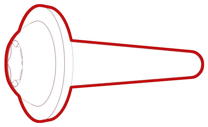 24 Nm (17.7 lbs-ft)
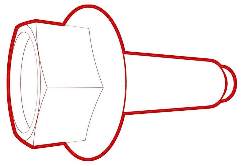 24 Nm (17.7 lbs-ft)
 - Install the LH rear sill panel trim. See Trim - Sill Panel - Rear - LH (Remove and Replace).
- Install the foam cover to the LH side of the ancillary bay.
- Install the 2nd row seat cushion. See Seat Cushion - Lower - 2nd Row (Remove and Replace).
- Install the rear underhood apron. See Underhood Apron - Rear (Remove and Replace).