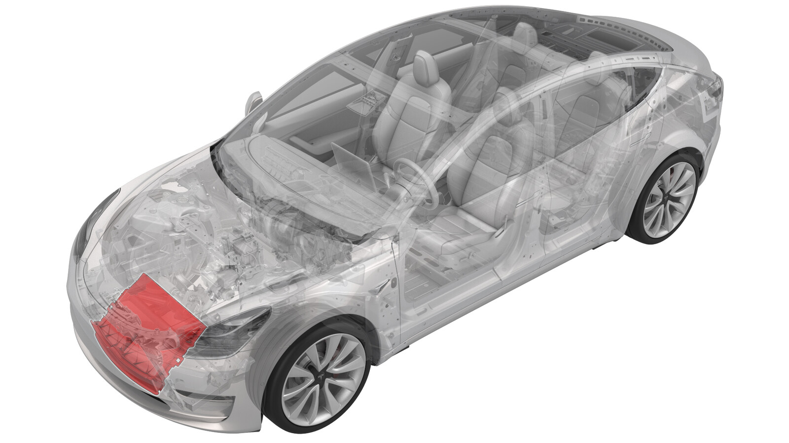
Active Grille Shutter (Remove and Replace)
 Correction code
18500602
0.84
NOTE: Unless otherwise explicitly
stated in the procedure, the above correction code and FRT reflect all of the work
required to perform this procedure, including the linked procedures. Do not stack correction codes unless
explicitly told to do so.
NOTE: See Flat Rate
Times to learn more about FRTs and how they are created.
NOTE: See Personal Protection to make sure wearing proper PPE when
performing the below procedure. NOTE: See Ergonomic Precautions for safe and healthy working
practices.
Correction code
18500602
0.84
NOTE: Unless otherwise explicitly
stated in the procedure, the above correction code and FRT reflect all of the work
required to perform this procedure, including the linked procedures. Do not stack correction codes unless
explicitly told to do so.
NOTE: See Flat Rate
Times to learn more about FRTs and how they are created.
NOTE: See Personal Protection to make sure wearing proper PPE when
performing the below procedure. NOTE: See Ergonomic Precautions for safe and healthy working
practices.
- 2023-11-16: Updated the whole procedure according to the latest validation.
| Description | Torque Value | Recommended Tools | Reuse/Replace | Notes |
|---|---|---|---|---|
| 12V negative terminal nut |
 6 Nm (4.4 lbs-ft) |
|
Reuse | |
| Bolts (x2) that attach the lower LH and RH of the cooling fan module to the ankle catcher |
10 Nm (7.4 lbs-ft) |
|
Reuse |
Only
technicians who have completed all required certification courses are permitted to
perform this procedure. Tesla recommends third party service provider technicians
undergo equivalent training before performing this procedure. For more information on
Tesla Technician requirements, or descriptions of the subject matter for third parties,
see HV Certification Requirements. Proper personal protective equipment (PPE) and insulating HV
gloves with a minimum rating of class 0 (1000V) must
be worn at all times a high voltage cable, busbar, or fitting is handled. Refer to Tech Note TN-15-92-003, High Voltage Awareness
Care Points
for additional safety
information.
Remove
- Put the vehicle on a 2-post lift.
- Open all doors and lower all windows.
- Move the LH and RH front seats forward.
-
Remove the 2nd row seat cushion and disconnect the harness.
NoteSlide the locking tabs to the left of the vehicle while lifting up the seat bench. Newer models have connectors on both sides of bench while older models have 2 connectors on one side of the bench.
- Remove the underhood storage unit. See Underhood Storage Unit (Remove and Replace)
-
Disconnect the 12V negative terminal.
NoteEnsure the vehicle is in Park and the climate control system is Off. Ensure the vehicle is not charging before disconnecting 12V.TIpUse of the following tool(s) is recommended:
- 10 mm deep socket
-
Disconnect the high-voltage controller (HVC) logic connector, and install the logic cap.
NoteRelease the locking tab, then push the handle downward to release the connector.
- Remove the front aero shield panel. See Panel - Aero Shield - Front (Remove and Replace).
- Remove the front valance. See Valance - Front Fascia (Remove and Replace).
- Install towel to the front of subframe to protect the cooling fan in later steps.
-
Remove the bolts (x2) that attach the lower LH and RH of the cooling fan module to the ankle catcher, and then remove the cooling fan module from the vehicle.
NoteLift up on the cooling fan module to ease the removal of the bolts.TIpUse of the following tool(s) is recommended:
- 8 mm 12-point deep socket
- 8 mm socket
Figure 1. LH Side Figure 2. RH Side - Lower the vehicle to a comfortable working height and set the lift onto locks.
-
Disconnect the active grille shutter electrical connector.
-
Release the side clips that attach the active grille shutter to the condenser fan module.
Figure 3. Other components hidden for clarity -
Release the lower clips that attach the active grille shutter to the bottom of the condenser fan module.
NoteMake sure that the active grille shutter assembly is pushed up and away from the cooling fan module.
Figure 4. View is from under vehicle; other components hidden for clarity -
Release the upper clips that attach the active grille shutter to the top of the condenser fan module.
Figure 5. Other components hidden for clarity -
While tilting the condenser fan module downwards, carefully release and remove the active grille shutter from underneath the vehicle.
CAUTIONWhile removing the active grille shutter, take care not to damage the radiator fins.
Install
-
Position the active grille shutter on the cooling fan module, and then install the lower clips that attach the active grille shutter to the bottom of the condenser fan module.
Figure 6. View is from under vehicle; other components hidden for clarity -
Install the side clips that attach the active grille shutter to the condenser fan module.
Figure 7. Other components hidden for clarity -
Install the upper clips that attach the active grille shutter to the top of the condenser fan module.
Figure 8. Other components hidden for clarity -
Raise the vehicle to a comfortable working height, and lower the lift onto locks.
CAUTION
Make sure there is an audible click of the locks on both sides before lowering, otherwise the vehicle may tilt to one side.
Make sure that the doors are clear of surrounding objects.
-
From underneath the vehicle, move the cooling fan module into position, and then hand start the bolts (x2) that attach the cooling fan module to the ankle catcher.
NoteAssistance is recommended.NoteLift up on the cooling fan module to ease the installation of the bolts.NoteMake sure the lower edge of the active grille shutter is flush with the lower edge of the cooling fan module.
-
Torque the bolts (x2) that attach the lower LH and RH of the cooling fan module to the ankle catcher.10 Nm (7.4 lbs-ft)NoteLift up on the cooling fan module to ease the installation of the bolts.TIpUse of the following tool(s) is recommended:
- 8 mm 12-point deep socket
- 8 mm socket
Figure 9. LH Side Figure 10. RH Side - Remove the towel from the front of subframe.
- Install the front fascia valance. See Valance - Front Fascia (Remove and Replace).
- Install the front aero shield panel. See Panel - Aero Shield - Front (Remove and Replace).
-
Connect the electrical harness to the active grille shutter electrical connector.
-
Remove the logic cap, and then connect the HVC logic connector.
NoteAlign the connector, then pull the handle to the locking position. Get the connector fully seated.
-
Install the 12V cap to the ancillary bay, and then connect the 12V negative terminal.6 Nm (4.4 lbs-ft)TIpUse of the following tool(s) is recommended:
- 10 mm deep socket
- Connect the 2nd row seat cushion harness and install the 2nd row seat cushion.
- Move the LH and RH front seats to original position.
-
Perform the following
routine using Service Mode or Toolbox (see 0005 - Service Modes):
PROC_VCFRONT_X_LOUVER-CALIBRATIONvia Toolbox:(link)
NoteOnce complete, select the ‘X’ at the top right of the window to close.
-
Perform the following
routine using Service Mode or Toolbox (see 0005 - Service Modes):
TEST-SELF_VCFRONT_X_THERMAL-PERFORMANCEvia Service Mode:Thermal ➜ Actions ➜ Test Thermal Performancevia Service Mode Plus:
- Drive Inverter ➜ Front Drive Inverter Replacement ➜ Thermal System Test
- Drive Inverter ➜ Rear Drive Inverter Replacement ➜ Thermal System Test
- Drive Inverter ➜ Rear Left Drive Inverter Replacement ➜ Thermal System Test
- Drive Inverter ➜ Rear Right Drive Inverter Replacement ➜ Thermal System Test
- Drive Unit ➜ Front Drive Unit Replacement ➜ Thermal System Test
- Drive Unit ➜ Rear Drive Unit Replacement ➜ Thermal System Test
- Disable Service Mode. See Service Mode.
- Install the underhood storage unit. See Underhood Storage Unit (Remove and Replace)
- Raise all windows and close all doors.
- Remove the vehicle from the lift.