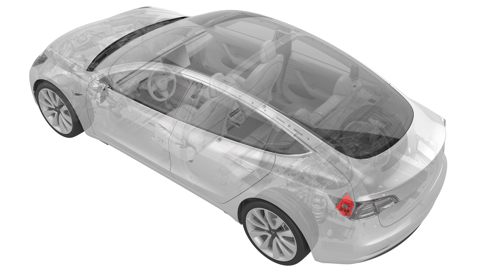
Deadfronts - Pin - Charge Port (NA) (Damaged) (Remove and Replace)
 Correction code
44012132
0.24
NOTE: Unless otherwise explicitly
stated in the procedure, the above correction code and FRT reflect all of the work
required to perform this procedure, including the linked procedures. Do not stack correction codes unless
explicitly told to do so.
NOTE: See Flat Rate
Times to learn more about FRTs and how they are created.
NOTE: See Personal Protection to make sure wearing proper PPE when
performing the below procedure. NOTE: See Ergonomic Precautions for safe and healthy working
practices.
Correction code
44012132
0.24
NOTE: Unless otherwise explicitly
stated in the procedure, the above correction code and FRT reflect all of the work
required to perform this procedure, including the linked procedures. Do not stack correction codes unless
explicitly told to do so.
NOTE: See Flat Rate
Times to learn more about FRTs and how they are created.
NOTE: See Personal Protection to make sure wearing proper PPE when
performing the below procedure. NOTE: See Ergonomic Precautions for safe and healthy working
practices.
Equipment:
- 1552269-00-A Dead Front Install Tool, Model 3
- 1076921-00-B Insulation Multimeter, Fluke 1507 (NA)
- 1108272-00-B Cap, Logic Conn, Inv, 3DU
- 1130480-00-A Test Probes, Slim, Fluke TP38
Only
technicians who have completed all required certification courses are permitted to
perform this procedure. Tesla recommends third party service provider technicians
undergo equivalent training before performing this procedure. For more information on
Tesla Technician requirements, or descriptions of the subject matter for third parties,
see HV Certification Requirements. Proper personal protective equipment (PPE) and insulating HV
gloves with a minimum rating of class 0 (1000V) must
be worn at all times a high voltage cable, busbar, or fitting is handled. Refer to Tech Note TN-15-92-003, High Voltage Awareness
Care Points
for additional safety
information.
Remove all jewelry (watches, bracelets, rings, necklaces, earrings, ID tags, piercings, etc.) from your person, and all objects (keys, coins, pens, pencils, tools, fasteners, etc.) from your pockets before performing any procedure that exposes you to high voltage.
Proper Personal Protective Equipment (PPE) is required to perform this procedure:
- High Voltage (HV) insulating gloves
- Leather glove protectors
- High voltage glove tester
- Safety glasses
- Electrical hazard rated safety shoes
A glove inflator is the only recommended way to test HV gloves. Both HV gloves must pass testing before beginning this procedure. If either glove does not pass the air check, discard the pair.
Make sure that the HV gloves are not expired. HV gloves can be used up to 12 months after the testing date printed on the glove, but only 6 months after first use even if the gloves are still within the 12-month period.
Remove
- Open the LH doors and lower all the windows.
- Remove the rear underhood apron. See Underhood Apron - Rear (Remove and Replace).
-
Release the tab on the RH
side of the 2nd row lower seat cushion to release the RH front edge of the
cushion from the vehicle, and then use the 12V cap to prop the lower
cushion.
- Open the charge port door.
- Disconnect 12V power. See 12V/LV Power (Disconnect and Connect).
- Put on the high voltage gloves, leather outer gloves, and other high voltage PPE, and do not remove them until instructed to do so.
- Perform the charge port voltage check procedure. See Charge Port Voltage Check.
-
Measure 8 mm from the tip of the 4mm0.75 tap, and then use a paint pen to
mark a ring around the threads of the tap.
-
Attach the tap to a tap
handle or tap wrench.
-
Use right-angle needle nose
pliers to prevent the charge port pin deadfront from turning, and then
thread the tap into the deadfront, up to the paint mark.
-
Remove the tap handle or tap wrench from the tap.
-
Carefully chuck the tap into
a battery powered drill.
-
Lightly pull on the charge
port pin deadfront and spin the drill clockwise to shear
the charge port pin deadfront retention ring off, and then remove the
deadfront from the charge port pin.
-
Remove the charge port pin
deadfront from the tap.
- Remove the tap from the drill.
- Repeat step 9 through step 15 for the other charge port pin deadfront.
-
Inspect the charge port for any broken pin deadfront pieces or debris and remove from the charge port assembly with an ESD-safe vacuum.
NoteSome pieces might require use of the needle nose pliers, curved surgical clamps, or a pocket screw driver to dislodge.
Install
-
Install a new charge port
pin deadfront onto the pin of the deadfront installation tool as
shown.
TIpAlternatively, the following tool(s) can be used:
- 3mm hex socket
- 6 inch extension
-
Use a dead blow hammer to
fully seat the charge port pin deadfront into the charge port pin.
- Repeat steps 1 and 2 for the other new charge port pin deadfront.
- Remove the leather outer gloves, high voltage gloves, and other high voltage PPE.
- Reconnect 12V power. See 12V/LV Power (Disconnect and Connect).
- Install the rear underhood apron. See Underhood Apron - Rear (Remove and Replace).
- Install the 2nd row lower seat cushion. See Seat Cushion - Lower - 2nd Row (Remove and Replace).
- Verify that the vehicle charges normally.