2026-06-26
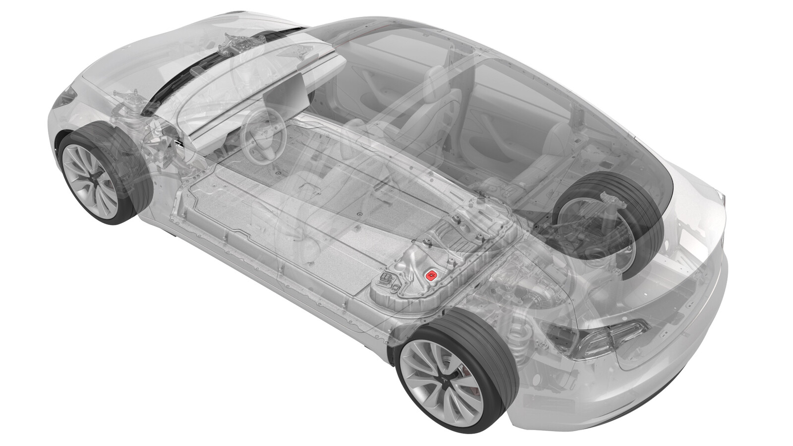
Ancillary Bay Air Leak Test (Inspection)
 Correction code
16100400
0.54
NOTE: Unless otherwise explicitly stated in the procedure, the correction code and FRT listed above reflect all of the work required to perform this procedure, including the linked procedures. Do not stack correction codes unless explicitly told to do so.
NOTE: See Flat Rate Times to learn more about FRTs and how they are created.
NOTE: See Personal Protection to make sure you
are wearing proper PPE when performing the procedure below.
NOTE: See Ergonomic Precautions for safe and healthy working practices.
Correction code
16100400
0.54
NOTE: Unless otherwise explicitly stated in the procedure, the correction code and FRT listed above reflect all of the work required to perform this procedure, including the linked procedures. Do not stack correction codes unless explicitly told to do so.
NOTE: See Flat Rate Times to learn more about FRTs and how they are created.
NOTE: See Personal Protection to make sure you
are wearing proper PPE when performing the procedure below.
NOTE: See Ergonomic Precautions for safe and healthy working practices.
- 2026-03-12: Added 1586825-00-A DCFC Leak Plug for models with DCFC bus bars.
Equipment:
- 1026636-00-A Pack Enclosure Leak Tester, HV Battery
- 1140501-00-A Pack Kit, Enclosure, Leak Test, HV Battery, Complete
- 1144879-00-A Kit, Encl Leak Test Adapters, HV Battery
- 1586825-00-A DCFC Leak Plug (models with DCFC Bus Bars)
- 1455410-00-A Kit, Dummy Plug
- 1108272-00-B Cap, Logic Conn, Inv, 3DU
- 1813553-00-A MYSP Platter, Enclosure Leak Test, Air Splitter
Procedure
- Perform the vehicle electrical isolation procedure. See Vehicle HV Disablement Procedure.
-
Make sure that the logic
connector cap is snug on the high voltage controller connector to prevent
leaks.
- Remove the rear HV battery skid plate. See Skid Plate - HV Battery - Rear (Remove and Replace).
- Make sure that the high voltage connectors along the rear of the HV battery are fully seated and securely latched.
- Install the rear HV battery skid plate. See Skid Plate - HV Battery - Rear (Remove and Replace).
- Remove the ancillary bay HV cap. See Cap - HV - Ancillary Bay (Remove and Replace).
- Remove the LH rear sill panel trim. See Trim - Sill Panel - Rear - LH (Remove and Replace).
-
Release the clips that
attach the low voltage electrical harness to the charge port to HV battery
harness bracket at the ancillary bay.
-
Remove the bolts that attach
the charge port to HV battery harness bracket at the ancillary bay, and then
remove the bracket from the vehicle.
-
Slide the release to unlock
the DC input connector handle of the charge port to HV battery harness from
the secured position.
-
Fully raise the handle on
the DC input connector.
- Remove the DC input connector from the ancillary bay DC input header.
- If the charge port to HV battery harness has a 3-phase connector, continue to the next step, otherwise skip to step 17.
-
Slide the release to unlock
the 3-phase connector handle of the charge port to HV battery harness from
the secured position.
-
Fully raise the handle on
the 3-phase connector.
- Remove the 3-phase connector from the ancillary bay 3-phase header.
-
Release the clip that
attaches the charge port to HV battery wiring harness to the LH lower
C-pillar.
-
Install the charge port
dummy plug onto the DC input assembly.
-
If the charge port to HV
battery harness has a 3-phase connector, install a dummy plug to the 3-phase
header.
-
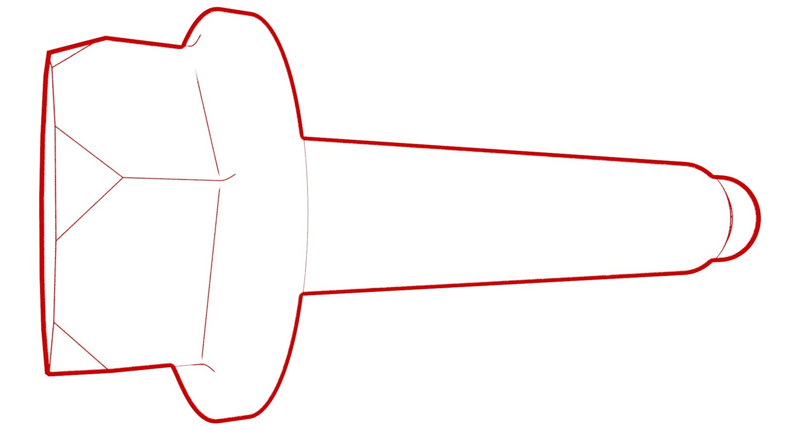
Remove and discard the
breather plug from the ancillary bay probe lid cover.
-
Install the leak test adapter into the ancillary bay probe lid cover.
-
Connect the pack enclosure
leak tester to the leak test adapter.
- Close both valves on the pack enclosure leak tester by turning valve knobs to a vertical position.
-
Connect the pack enclosure
leak tester to air supply.
NoteMake sure the pack enclosure leak tester valves are both in the closed position.
- Turn the inlet valve to the open position by turning the valve knob to a horizonal position.
- Set the pack enclosure leak tester to 0.15 psi.
- Open the outlet valve to inject air into the ancillary bay, and allow 60 seconds for the pressure to stabilize to 0.15 psi.
- Close the inlet valve and wait 45 seconds for pressure to settle.
- Record value of starting pressure.
- Wait 60 seconds to test pressure and record value of ending pressure.
-
Subtract the ending pressure from the starting pressure, and if:
- The difference is greater than 0.0231 psi, check the hose, adapter, and plug fittings, close the outlet valve and open the inlet valve, check the pack enclosure leak tester pressure, and then retest from step 27. If the difference is still greater than 0.0231 psi, further investigate possible causes for the pressure leak, starting with Toolbox article 41588. If the cause for the pressure leak can still not be found and resolved, escalate a Toolbox session.
- The difference is 0.0231 psi or less, continue the procedure.
- Disconnect the air supply from the pack enclosure leak tester.
-
Disconnect the pack
enclosure leak tester from the leak test adapter.
-
Remove the leak test adapter from the ancillary bay probe lid cover.
-
Install a new breather plug
onto the ancillary bay probe lid cover.
-
If installed, remove the dummy plug from the 3-phase header.
-
Remove the charge port dummy
plug from the DC input assembly.
-
Fully raise the handle on
the DC input connector of the charge port to HV battery harness.
-
Use both hands to firmly
connect the DC input connector of the charge port to HV battery harness to
the ancillary bay DC input header.
CAUTIONMake sure that the connector fits the header squarely and tightly.
-
While pressing the DC input
connector onto the DC input header, fully lower the handle.
CAUTIONMake sure that the handle does not bind as it is lowered.
-
Slide the release to lock
the DC input connector handle in the secured position.
-
Verfiy that the connector is
fully seated, and compare both sides of the connector, that it is properly
latched in place.
NoteAn improperly seated connector might lead to connector damage and charging problems later on.
- If the charge port to HV battery harness has a 3-phase connector, continue to the next step, otherwise skip to step 49.
-
Fully raise the handle on
the 3-phase connector of the charge port to HV battery harness.
-
Use both hands to firmly
connect the 3-phase connector of the charge port to HV battery harness to
the ancillary bay 3-phase header.
CAUTIONMake sure that the connector fits the header squarely and tightly.
-
While pressing the 3-phase
connector onto the 3-phase header, fully lower the handle.
CAUTIONMake sure that the handle does not bind as it is lowered.
-
Slide the release to lock
the 3-phase connector handle in the secured position.
-
Verfiy that the connector is
fully seated, and compare both sides of the connector, that it is properly
latched in place.
NoteAn improperly seated connector might lead to connector damage and charging problems later on.
-
Fasten the clip that
attaches the charge port to HV battery wiring harness to the LH lower
C-pillar.
-
Install the charge port to
HV battery wiring harness bracket to the ancillary bay, and then install the
bolts that attach the bracket to the ancillary bay.
 10 Nm (7.4 lbs-ft)
 -
Fasten the clips that attach
the low voltage electrical harness to the charge port to HV battery harness
bracket at the ancillary bay.
- Install the LH rear sill panel trim. See Trim - Sill Panel - Rear - LH (Remove and Replace).
- Connect 12 V power. See 12V/LV Power (Disconnect and Connect).
- Install the ancillary bay HV and ancillary bay 12V caps.