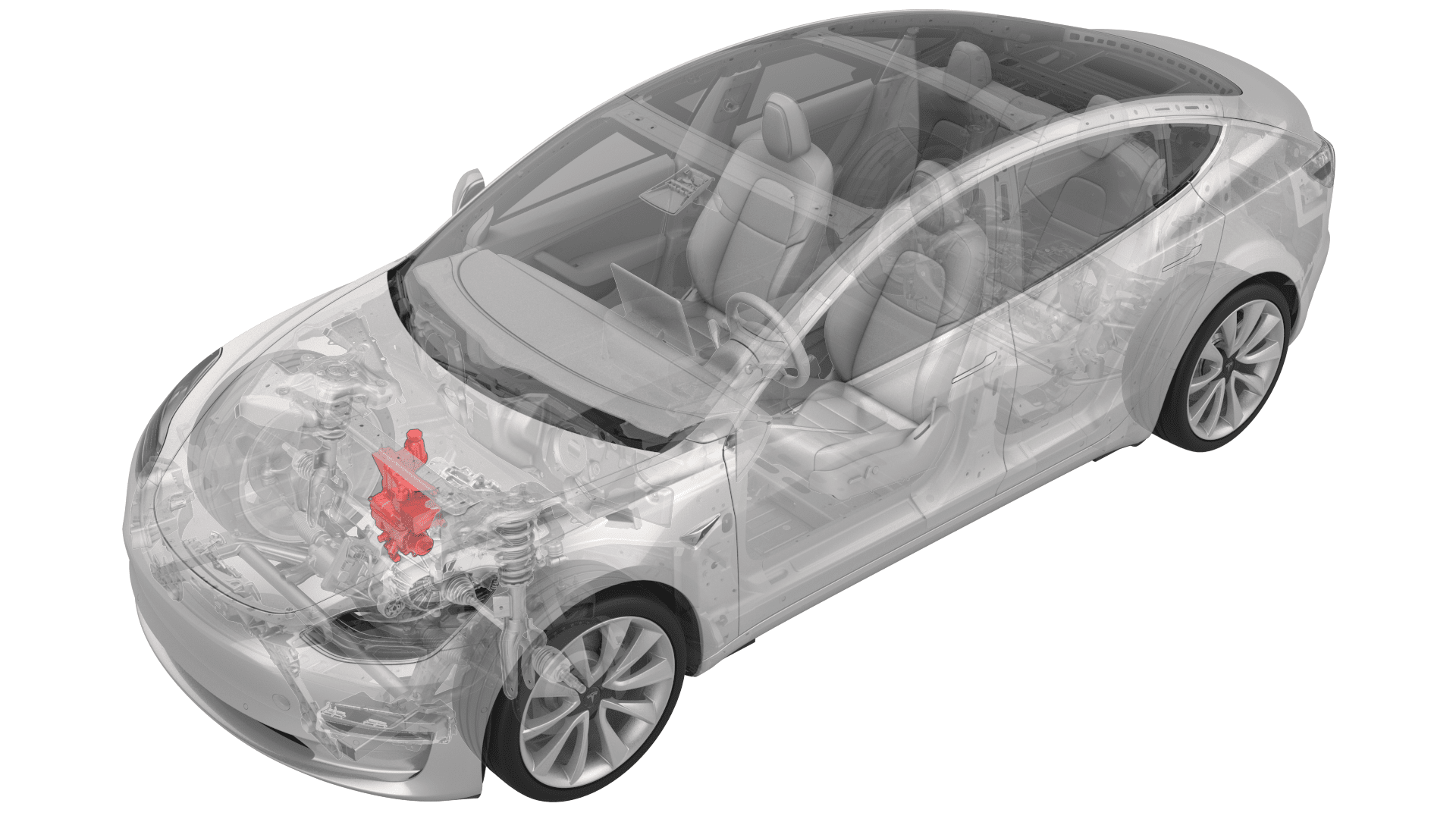
Superbottle (Dual Motor) (Remove and Replace)
 Correction code
18301512
2.76
NOTE: Unless otherwise explicitly
stated in the procedure, the above correction code and FRT reflect all of the work
required to perform this procedure, including the linked procedures. Do not stack correction codes unless
explicitly told to do so.
NOTE: See Flat Rate
Times to learn more about FRTs and how they are created.
NOTE: See Personal Protection to make sure wearing proper PPE when
performing the below procedure. NOTE: See Ergonomic Precautions for safe and healthy working
practices.
Correction code
18301512
2.76
NOTE: Unless otherwise explicitly
stated in the procedure, the above correction code and FRT reflect all of the work
required to perform this procedure, including the linked procedures. Do not stack correction codes unless
explicitly told to do so.
NOTE: See Flat Rate
Times to learn more about FRTs and how they are created.
NOTE: See Personal Protection to make sure wearing proper PPE when
performing the below procedure. NOTE: See Ergonomic Precautions for safe and healthy working
practices.
Equipment:
- 1135762-00-A Kit, Svc Plug, Cooling Hose, Model 3
- 2024-08-21: Added O-ring part numbers 1111740-00-A and 1111737-00-A for the suction/liquid line fitting.
- 2024-03-22: Updated coolant valve self-test Toolbox routine.
- 2023-08-14: Added note to 12V battery install step.
Remove
- Remove the 2nd row lower seat cushion. See Seat Cushion - Lower - 2nd Row (Remove and Replace).
- Remove the rear underhood apron. See Underhood Apron - Rear (Remove and Replace).
- Remove the cabin intake duct. See Duct - Upper - Cabin Intake (Remove and Replace).
- Remove the underhood storage unit. See Underhood Storage Unit (Remove and Replace).
-
Recover the A/C refrigerant. See A/C Refrigerant (Recovery and Recharge).
NoteRecover the refrigerant while continuing this procedure.
-
Remove the superbottle cap.
- Disconnect 12V power. See 12V/LV Power (Disconnect and Connect).
- Remove the 12V auxiliary battery. See 12V/LV Battery (Remove and Replace).
-
Remove the shock tower brace. See Brace - Shock Tower (Non-Heat Pump) (Remove and Replace).
NoteDo not separate the compressor body bracket from the strut tower brace.
- Remove the front aero shield. See Panel - Aero Shield - Front (Remove and Replace).
- Partially lower the vehicle, and then position a coolant drain container underneath the RH front side of the vehicle.
-
Install a foldable funnel underneath the heat exchanger, as shown.
NoteMake sure the foldable funnel covers the front drive unit 12V connector, steering rack, and is positioned to catch fluid from the heat exchanger coolant outlet.
-
Release the clip that connects the front drive unit heat exchanger-superbottle hose to the heat exchanger coolant outlet, and then drain the coolant into the coolant drain container.
- Plug the front drive unit heat exchanger-superbottle hose and the heat exchanger coolant outlet.
-
Release the clip and disconnect the radiator inlet hose from the front left of the superbottle.
-
Release the clip and disconnect the radiator outlet hose from the front right of the superbottle.
-
Disconnect the electrical harness from the chiller and EXV assembly hose coolant temperature sensor connector.
-
Release the clip and disconnect the coolant hose from the chiller and EXV assembly.
-
Disconnect the electrical harness from the HV battery coolant pump connector.
-
Disconnect the electrical harness from the powertrain coolant pump connector.
-
Disconnect the electrical harness from the powertrain pump to sill hose coolant temperature sensor connector.
TIpTilt the superbottle toward the front of the vehicle for better access.
-
Release the clip and disconnect the powertrain pump-sill connector hose from the rear right of the superbottle.
-
Release the clip that attaches the suction/liquid lines to the superbottle.
-
Release the clip that attaches the electrical harness to the RH side of the superbottle.
-
Disconnect the electrical harness from the superbottle level sensor connector.
-
Release the clip and disconnect the battery return hose from the rear left of the superbottle.
TIpTilt the superbottle toward the front of the vehicle for better access.
-
Release the clip that attaches the battery return hose to the superbottle.
-
Release the clip that attaches the electrical harness to the lower LH side of the superbottle.
TIpLift the superbottle for better access.
-
Disconnect the electrical harness from the 5-way valve actuator connector.
TIpLift the superbottle for better access.WarningMake sure that the refrigerant has fully recovered before continuing this procedure.
-
Remove the bolt that attaches the suction/liquid line to the chiller and EXV assembly, and then remove the line from the chiller and EXV assembly.
-
Remove and discard the o-rings from the suction/liquid line fitting.
-
Remove the superbottle from the vehicle.
-
Release the clip that attaches the front drive unit heat exchanger-superbottle hose to the superbottle.
-
Release the clip and disconnect the front drive unit heat exchanger-superbottle hose from the superbottle.
Install
-
Connect the front drive unit heat exchanger-superbottle hose to the superbottle, and then install the clip.
-
Install the clip that attaches the front drive unit heat exchanger-superbottle hose to the superbottle.
-
Position the superbottle in the vehicle.
-
Connect the electrical harness to the 5-way valve actuator connector.
-
Install the clip that attaches the electrical harness to the lower LH side of the superbottle.
-
Install the clip that attaches the battery return hose to the superbottle.
-
Connect the battery return hose to the superbottle, and then install the clip.
-
Connect the electrical harness to the superbottle level sensor connector.
-
Install the clip that attaches the electrical harness to the RH side of the superbottle.
-
Install the clip that attaches the suction/liquid lines to the superbottle.
-
Connect the powertrain pump-sill connector hose to the superbottle, and then install the clip.
-
Connect the electrical harness to the powertrain pump-sill connector hose coolant temperature sensor.
-
Connect the electrical harness to the powertrain coolant pump connector.
-
Connect the electrical harness to the HV battery coolant pump connector.
-
Connect the coolant hose to the chiller and EXV assembly, and then install the clip.
NotePerform a push-pull test on the hose to verify that the hose is fully attached.
-
Connect the electrical harness to the chiller and EXV assembly hose coolant temperature sensor.
-
Connect the radiator outlet hose to the front right of the superbottle, and then install the clip.
-
Connect the radiator inlet hose to the front left of the superbottle, and then install the clip.
- Remove the plugs from the front drive unit heat exchanger-superbottle hose and coolant port.
-
Connect the front drive unit heat exchanger-superbottle hose to the heat exchanger, and then install the clip.
- Remove the coolant drain container from underneath the vehicle, and then install the front aero shield panel. See Panel - Aero Shield - Front (Remove and Replace).
-
Install new o-rings onto the suction/liquid line fitting, install the suction/liquid line fitting into the chiller and EXV assembly, and then install the bolt that attaches the suction/liquid line to the chiller and EXV assembly.
 22 Nm (16.2 lbs-ft)
 - Install the shock tower brace. See Brace - Shock Tower (Non-Heat Pump) (Remove and Replace).
- Connect the A/C lines to the vehicle, and then initiate an A/C vacuum and leak test.
-
Install the 12V battery, but do not connect 12V power yet. See 12V/LV Battery (Remove and Replace).
Note12V power will be connected in a later step.
- When the A/C vacuum and leak test is complete, recharge the refrigerant. See A/C Refrigerant (Recovery and Recharge).
- Connect 12V power. See 12V/LV Power (Disconnect and Connect).
- Perform a cooling system vacuum refill. See Cooling System (Vacuum Refill).
- Connect a charge cable to the vehicle.
- Connect a laptop with Toolbox to the vehicle.
- Using Toolbox, run the coolant valve actuator self-test, "TEST-SELF_VCFRONT_X_THERMAL-COOLANT-VALVEvia Toolbox:(link)."
-
In Toolbox, click the play button next to TEST-SELF_VCFRONT_X_THERMAL-PERFORMANCEvia Service Mode:Thermal ➜ Actions ➜ Test Thermal Performancevia Service Mode Plus:
- Drive Inverter ➜ Front Drive Inverter Replacement ➜ Thermal System Test
- Drive Inverter ➜ Rear Drive Inverter Replacement ➜ Thermal System Test
- Drive Inverter ➜ Rear Left Drive Inverter Replacement ➜ Thermal System Test
- Drive Inverter ➜ Rear Right Drive Inverter Replacement ➜ Thermal System Test
- Drive Unit ➜ Front Drive Unit Replacement ➜ Thermal System Test
- Drive Unit ➜ Rear Drive Unit Replacement ➜ Thermal System Test
- When the thermal performance test is complete, disconnect the charge cable from the vehicle.
- Disconnect the laptop from the vehicle.
- Install the underhood storage unit. See Underhood Storage Unit (Remove and Replace).
- Install the cabin intake duct. See Duct - Upper - Cabin Intake (Remove and Replace).
- Install the rear underhood apron. See Underhood Apron - Rear (Remove and Replace).
- Install the 2nd row lower seat cushion. See Seat Cushion - Lower - 2nd Row (Remove and Replace).