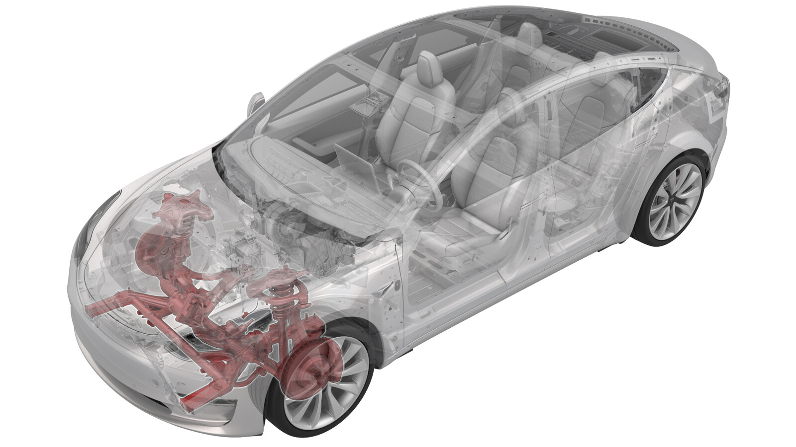
Subframe Assembly - Front (RWD) (Remove and Install)
 Correction code
30010301
1.80
NOTE: Unless otherwise explicitly
stated in the procedure, the above correction code and FRT reflect all of the work
required to perform this procedure, including the linked procedures. Do not stack correction codes unless
explicitly told to do so.
NOTE: See Flat Rate
Times to learn more about FRTs and how they are created.
NOTE: See Personal Protection to make sure wearing proper PPE when
performing the below procedure. NOTE: See Ergonomic Precautions for safe and healthy working
practices.
Correction code
30010301
1.80
NOTE: Unless otherwise explicitly
stated in the procedure, the above correction code and FRT reflect all of the work
required to perform this procedure, including the linked procedures. Do not stack correction codes unless
explicitly told to do so.
NOTE: See Flat Rate
Times to learn more about FRTs and how they are created.
NOTE: See Personal Protection to make sure wearing proper PPE when
performing the below procedure. NOTE: See Ergonomic Precautions for safe and healthy working
practices.
- 2024-04-11: Updated front lower lateral link to subframe torque specification.
- 2023-09-11: Update the bolt and nut that attach the LH front lower lateral link to the front subframe from discard to reuse.
Remove
- Raise and support the vehicle. See Raise Vehicle - 2 Post Lift.
- Loosen the LH and RH front wheels. Refer to Wheel Assembly (Remove and Install).
- Set the steering wheel in the straight ahead position, and then use a steering wheel holder to lock the steering wheel into position.
- Remove the 2nd row lower seat cushion. See Seat Cushion - Lower - 2nd Row (Remove and Replace).
- Remove the rear underhood apron. See Underhood Apron - Rear (Remove and Replace).
- Disconnect 12V power. See 12V/LV Power (Disconnect and Connect).
- Remove the hood latch cover. See Cover - Hood Latch (Remove and Replace).
- Remove the underhood storage unit. See Underhood Storage Unit (Remove and Replace).
-
Remove the bolt that attaches the intermediate shaft to the steering rack assembly, and then slide the intermediate shaft upwards.
-
Disconnect the electrical connectors from the steering rack assembly.
-
Remove the bolts that attach the upper portion of the front fascia to the vehicle.
- Raise the vehicle partially.
- Remove the LH and RH front wheels. See Wheel Assembly (Remove and Install).
- Remove the front aero shield panel. See Panel - Aero Shield - Front (Remove and Replace).
-
Release the clips (x2) that attach the valance to the body.
- Remove the LH and RH front wheel arch liners. See Wheel Arch Liner - Front - LH (Remove and Replace).
- Remove the front fascia. See Fascia - Front (Remove and Install).
-
Remove and discard the nut that attaches the LH tie rod end to the knuckle.
- Use a rubber hammer to remove the LH tie rod end from the vehicle.
-
Remove and discard the nut that attaches the LH front stabilizer bar to the front sway links, and then set the front sway links aside.
- Remove and discard the nut that attaches the RH tie rod end to the knuckle, and then set the tie rod end aside.
- Use a rubber hammer to remove the RH tie rod end from the vehicle.
-
Remove and discard the nut that attaches the RH front sway link to the front stabilizer bar, and then move the link aside.
- Raise the vehicle fully.
-
Remove the bolt and nut that attach the LH front lower compliance link to the front subframe, and then move the link aside.
-
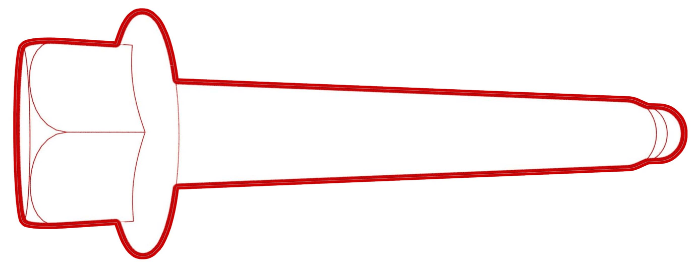
Remove and discard the bolts
that attach the LH front lower lateral link to the front subframe.
-
Remove the bolt and nut that attach the LH front spring and damper assembly to the lower control arm, and then move the LH front lower lateral link aside.
-
Remove the bolt and nut that attach the RH front lower compliance link to the front subframe, and then move the link aside.
-
Remove and discard the bolts
attach the RH front lower lateral link to the front subframe.
- Remove the bolt and nut that attach the RH front spring and damper assembly to the lower control arm, and then move the link aside.
- Put the subframe lifting tool (powertrain table and subframe fixture) underneath the front subframe area.
- Connect an air line to the subframe lifting tool.
-
With an assistant, latch the front subframe to the subframe lifting tool.
NoteMake sure to align the two guides.
-
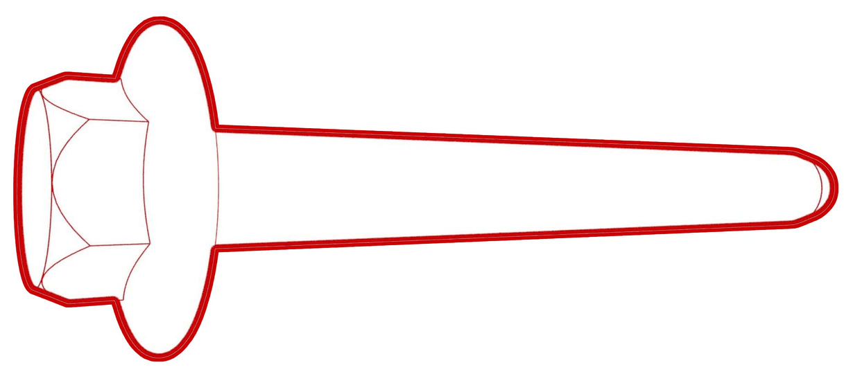
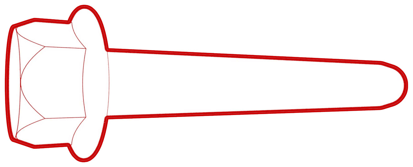
Remove the bolts that attach the front end carrier to the LH and RH front subframe crash can assemblies.
Figure 1. LH shown, RH similar -
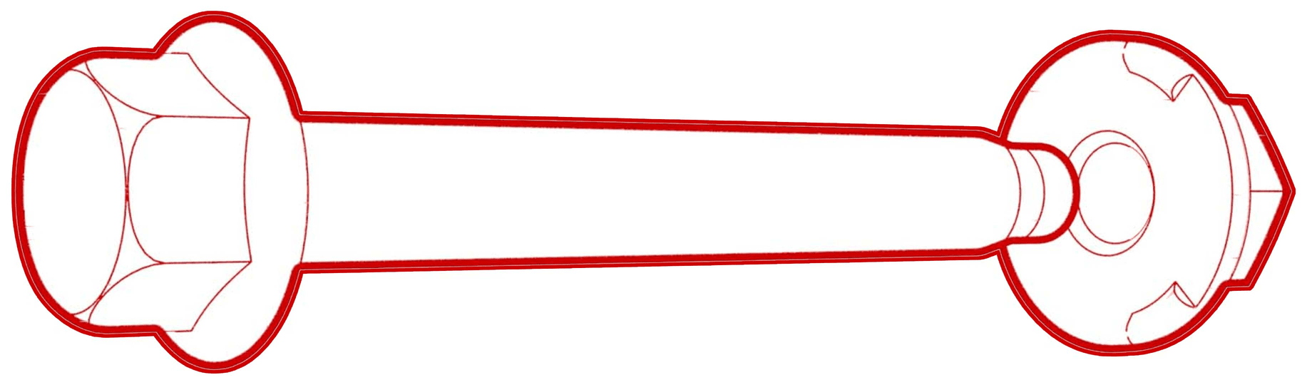
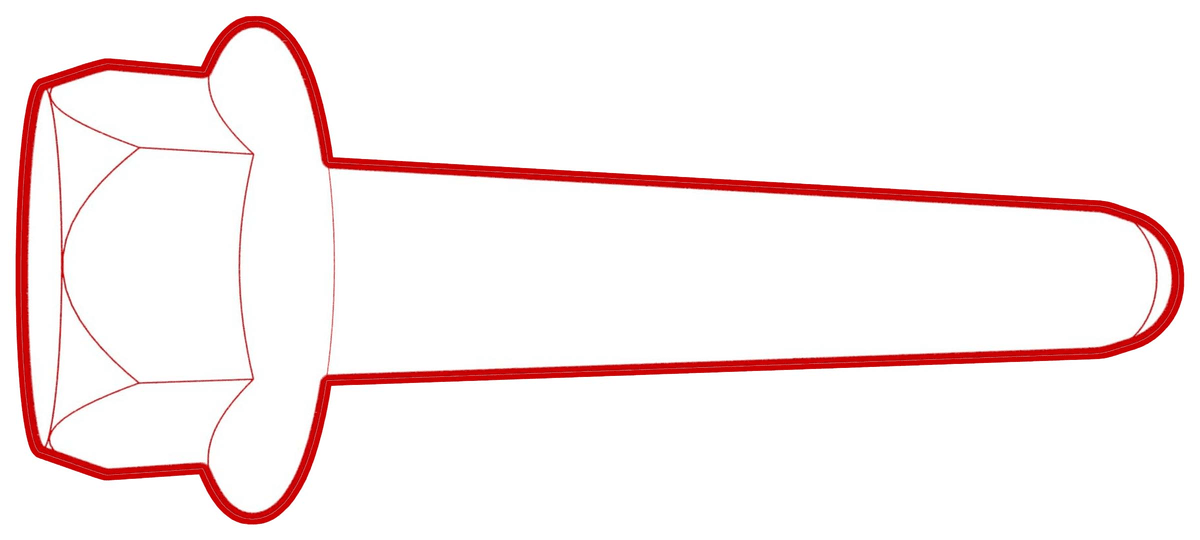
Remove the bolts that attach the LH and RH mid mount body kit to the body.
Figure 2. LH shown, RH similar -
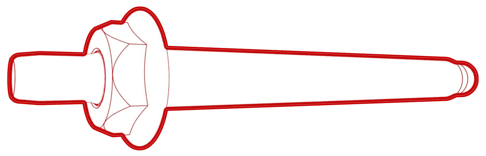
Remove the bolts that attach the front portion of the front subframe to the body.
 72 Nm (53.1 lbs-ft)
 -
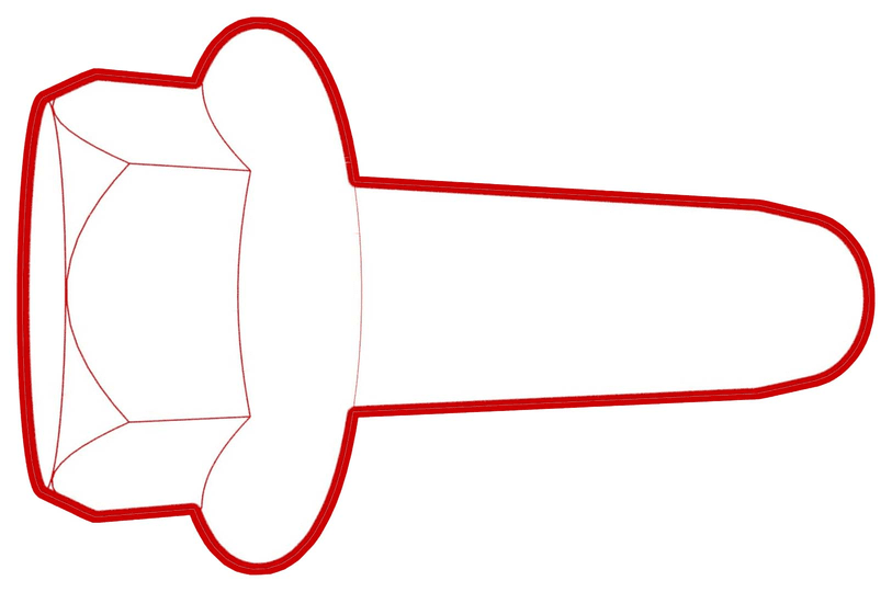
Remove the smaller bolts that attach the rear portion of the front subframe to the body.
-
Remove and discard the larger bolts that attach the rear portion of the front subframe to the body.
- With an assistant, lower the front subframe from the vehicle.
- Disconnect the air line from the subframe lifting tool.
-
Move the subframe lifting tool from underneath the vehicle.
Install
- Position the front subframe to the vehicle for installation.
- Connect an air line to the subframe lifting tool.
- With an assistant, raise the subframe lifting tool until the front subframe and body meet.
-
Hand-tighten the larger bolts that attach the rear portion of the front subframe to the body.
-
Hand-tighten the smaller bolts that attach the rear portion of the front subframe to the body.
-
Hand-tighten the bolts that attach the front portion of the front subframe to the body.
NoteAdjust the subframe lifting tool, if necessary.
-
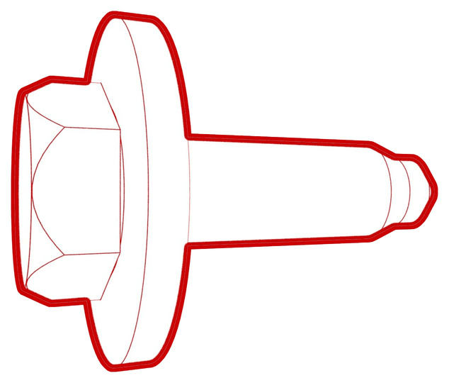
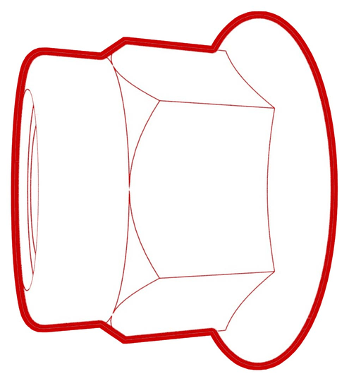
Install the bolts that attach the LH and RH mid mount kit to the body.
 50 Nm (36.9 lbs-ft)
Figure 3. LH shown, RH similar - Hand-tighten the bolts that attach the front end carrier to the LH and RH front subframe crash can assemblies.
-
Tighten the larger bolts that attach the rear portion of the front subframe to the body.
 125 Nm (92.2 lbs-ft)
 -
Tighten the smaller bolts that attach the rear portion of the front subframe to the body.
 50 Nm (36.9 lbs-ft)
 -
Tighten the bolts that attach the front portion of the front subframe to the body.
 72 Nm (53.1 lbs-ft)
 -
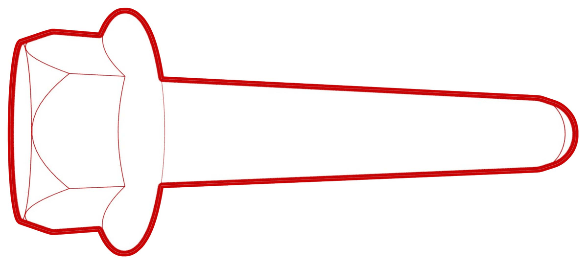
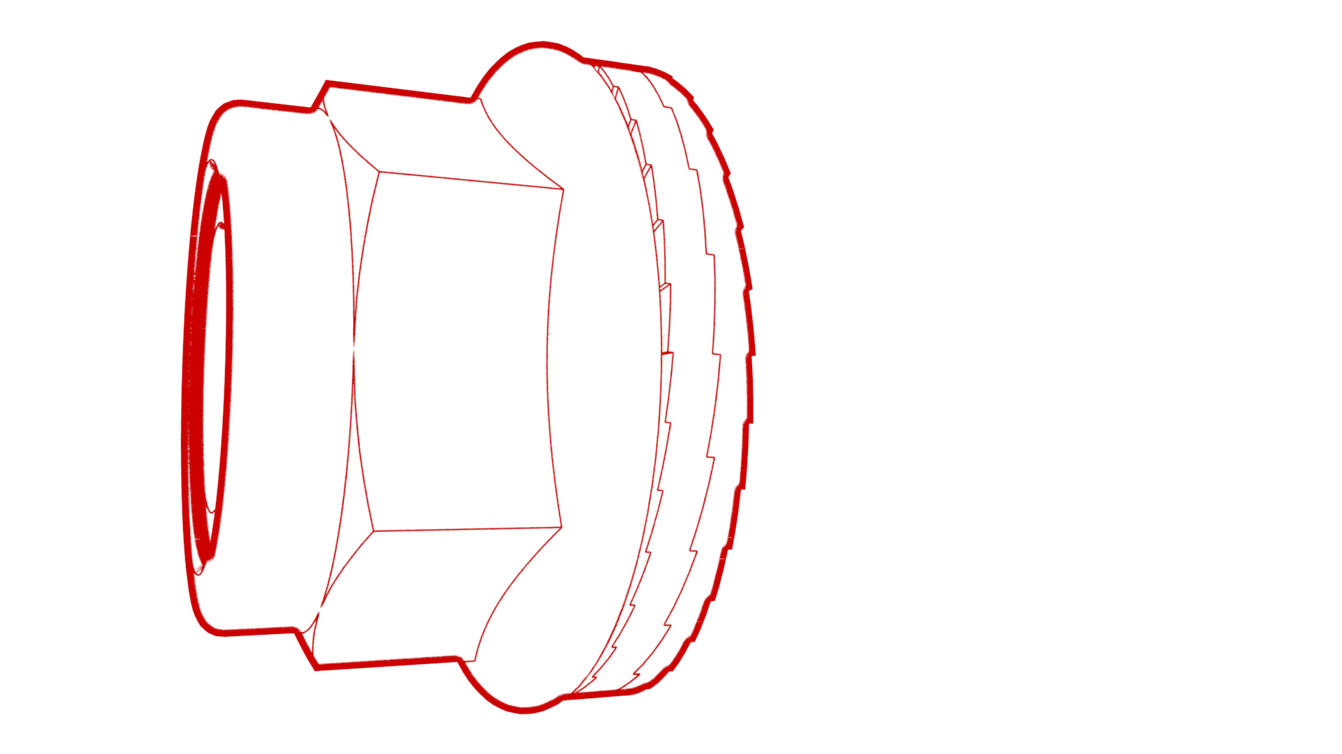
Tighten the bolts and nuts that attach the LH and RH crash can brackets to the front subframe.
 60 Nm (44.2 lbs-ft)
Figure 4. LH Shown, RH similar -
Tighten the bolts that attach the front end carrier to the LH and RH front subframe crash can assemblies.
 16 Nm (11.8 lbs-ft)
Figure 5. LH shown, RH similar - Lower the subframe lifting tool from the vehicle.
- Disconnect the air line from the subframe lifting tool, and then remove the subframe lifting tool from the vehicle.
- Hand-tighten the RH front lower lateral link.
-
Tighten the bolt and nut that attach the RH front spring and damper assembly to the lower control arm..
 106 Nm (78.2 lbs-ft)
 -
With an assistant, hand-tighten the bolts that attach the RH front lower lateral link to the front subframe.
NoteUse a punch tool to align the fasteners, if necessary.
- Hand-tighten the bolt and nut that attaches the RH front lower compliance link to the front subframe.
-
With an assistant, install the bolt and nut that attach the RH front lower compliance link to the front subframe.
 115 Nm (84.8 lbs-ft)
 115 Nm (84.8 lbs-ft)
 -
Tighten the bolts that
attach the RH front lower lateral link to the front subframe.
-
For 2123635-00-A:190 Nm (140.1 lbs-ft)
-
For 1109912-00-B, use only if
2123635-00-A is not
available:135 Nm (99.6 lbs-ft)
-
For 2123635-00-A:
-
Install the LH front lower lateral link, and then hand-tighten the bolt and nut that attach the LH front spring and damper assembly to the lower control arm.
 106 Nm (78.2 lbs-ft)106 Nm (78.2 lbs-ft)
 -
With an assistant, hand-tighten the bolts that attach the LH front lower lateral link to the front subframe.
NoteUse a punch tool to align the fasteners.
-
Install the LH front lower compliance link to the front subframe. With an assistant, install the bolt and nut that attach the LH front lower compliance link to the front subframe.
 115 Nm (84.8 lbs-ft)
 -
Tighten the bolts that
attach the LH front lower lateral link to the front subframe.
-
For 2123635-00-A:190 Nm (140.1 lbs-ft)
-
For 1109912-00-B, use only if 2123635-00-A is not available:135 Nm (99.6 lbs-ft)
-
For 2123635-00-A:
- Lower the vehicle partially.
- Put the front stabilizer bar onto the RH front stabilizer bar link.
-
Install new nut that attach the front stabilizer bar to the RH front stabilizer bar link.
 98 Nm (72.3 lbs-ft)
 - Put the front stabilizer bar onto the LH front stabilizer bar link.
-
Install new nut that attaches the front stabilizer bar to the LH front stabilizer bar link.98 Nm (72.3 lbs-ft)
- Put the LH tie rod end onto the knuckle.
-
Install new nut that attaches the LH tie rod end to the knuckle.
 180 Nm (132.7 lbs-ft)
 - Put the RH tie rod end onto the knuckle.
-
Install new nut that attaches the RH tie rod end to the knuckle.180 Nm (132.7 lbs-ft)
-
Remove the bolt that
attaches the LH front brake rotor to the hub.
-
Install the hub jack adapter
onto the LH front hub and hand-tighten the lug nuts.
-
Use an underhoist stand to
support the hub jack adapter.
-
Measure the distance between
the bottom of the fender and the center of the front axle and adjust the
underhoist stand so that the front suspension is set to ride height.
-
Tighten the bolt and nut
that attach the LH front damper to the lower control arm, and then mark the
bolt and nut with a paint pen.106 Nm (78.2 lbs-ft)
-
Remove the underhoist stand
from underneath the LH front suspension.
-
Remove the lug nuts that
attach the hub jack adapter, and then remove the hub jack adapter from the
vehicle.
-
Install the bolt that
attaches the LH front brake rotor to the hub.5 Nm (3.7 lbs-ft)
- Repeat step 35 through 42 for the RH side of the vehicle.
- Install the front fascia. See Fascia - Front (Remove and Install).
- Install the LH and RH front wheel arch liners. See Wheel Arch Liner - Front - LH (Remove and Replace).
-
Install the clips (x2) that attach the valance to the body.
- Install the front aero shield panel. See Panel - Aero Shield - Front (Remove and Replace).
- Hand-tighten the lug nuts that attach the LH and RH front wheels.
- Lower the vehicle until the tires are just above the ground, but the front tires are free to spin.
-
Install the bolts that attach the upper portion of the front fascia to the vehicle.
 4 Nm (2.9 lbs-ft)
 -
Connect the electrical connectors onto the steering rack assembly.
-
Slide the intermediate shaft downward to install it to the steering gear.
NoteMake sure that the intermediate shaft is aligned and fully seated onto the steering gear.NoteWith an assistant, align the intermediate shaft to the steering gear.
-
Install the bolt that attaches the intermediate shaft to the steering rack assembly, and then slide the intermediate shaft upwards.
 18 Nm (13.3 lbs-ft)
 - Install the LH and RH front wheels. Refer to Wheel Assembly (Remove and Install).
- Install the underhood storage unit. See Underhood Storage Unit (Remove and Replace).
- Install the hood latch cover. See Cover - Hood Latch (Remove and Replace).
- Connect 12V power. See 12V/LV Power (Disconnect and Connect).
- Install the cabin intake duct. See Duct - Upper - Cabin Intake (Remove and Replace).
- Install the rear underhood apron. See Underhood Apron - Rear (Remove and Replace).
- Install the 2nd row lower seat cushion. See Seat Cushion - Lower - 2nd Row (Remove and Replace).
- Move the driver and front passenger seats to their original positions.
- Remove the steering wheel holder and level from the steering wheel.
- Refer to the Alignment Requirement tables to determine whether an EPAS alignment check (EC) or four wheel alignment check (AC) is necessary. If performed, add the alignment check/adjust correction code as a separate activity to the SV. See Alignment Requirement - Suspension.