Cooling System (Drain and Refill)
 Correction code
18300100
1.08
NOTE: Unless otherwise explicitly
stated in the procedure, the above correction code and FRT reflect all of the work
required to perform this procedure, including the linked procedures. Do not stack correction codes unless
explicitly told to do so.
NOTE: See Flat Rate
Times to learn more about FRTs and how they are created.
NOTE: See Personal Protection to make sure wearing proper PPE when
performing the below procedure. NOTE: See Ergonomic Precautions for safe and healthy working
practices.
Correction code
18300100
1.08
NOTE: Unless otherwise explicitly
stated in the procedure, the above correction code and FRT reflect all of the work
required to perform this procedure, including the linked procedures. Do not stack correction codes unless
explicitly told to do so.
NOTE: See Flat Rate
Times to learn more about FRTs and how they are created.
NOTE: See Personal Protection to make sure wearing proper PPE when
performing the below procedure. NOTE: See Ergonomic Precautions for safe and healthy working
practices.
- 2023-05-22: Updated step to close pressure regulator valve, and added note that pressure regulator is fixed at 20 psi.
Remove
- Remove the 2nd row lower seat cushion. See Seat Cushion - Lower - 2nd Row (Remove and Replace).
- Remove the rear underhood apron. See Underhood Apron - Rear (Remove and Replace).
- Remove the cabin intake duct. See Duct - Upper - Cabin Intake (Remove and Replace).
- Disconnect 12V power. See 12V/LV Power (Disconnect and Connect).
- Remove the front aero shield. See Panel - Aero Shield - Front (Remove and Replace).
-
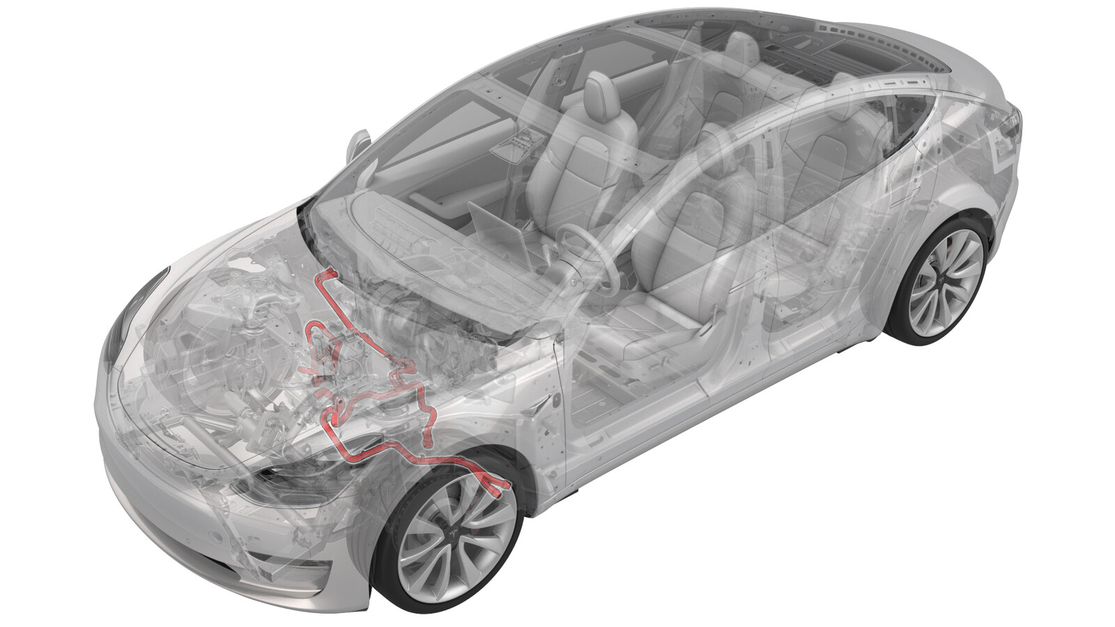
Release the push clips that attach the lower rear edge of the LH and RH wheel liners to the vehicle for access to the coolant hose.
Figure 1. LH side shown, RH similar - Pull the LH and RH wheel liners back, and then attach the liners to the subframe with bungee straps.
- Position the coolant drain container underneath the RH front side of the HV battery.
-
Release the spring clip to disconnect the powertrain return hose at the RH side of the vehicle, and then plug the female side of the hose.
- Attach a powertrain drain fitting adapter to the male side of the powertrain return hose, and then attach a hose extension to the adapter.
- Attach the hose extension to the coolant cart drain hose.
-
Release the spring clip to disconnect the rear powertrain supply hose at the RH side of the vehicle, and then plug the male side of the hose.
- Attach a powertrain flush fitting adapter to the female side of the rear powertrain supply hose.
-
Attach the powertrain flush
fitting adapter to the coolant pressure tester on the coolant cart, and then
close the pressure regulator valve.
NoteThe pressure regulator is fixed at 20 psi and is unadjustable.
-
Attach a compressed air line to the coolant pressure tester.
NoteMake sure the valve on the pressure regulator is closed.
- Open the valve on the powertrain drain fitting adapter.
- Slowly open the valve on the pressure regulator and allow coolant to drain out of the powertrain return hose.
- Close the valve on the pressure regulator when no more coolant is draining from the powertrain return hose.
- Remove the powertrain flush fitting adapter from the female side of the powertrain supply hose.
- Remove the powertrain drain fitting adapter from the male side of the powertrain return hose.
- Remove the plugs and attach the spring clips (x2) to reconnect both powertrain coolant hoses.
- Remove the powertrain drain fitting adapter from the cart drain hose, and then remove the powertrain flush fitting adapter from the cart pressure hose.
- Position the coolant drain container underneath the LH front side of the HV battery.
-
Release the spring clip to disconnect the HV battery return hose at the LH side of the vehicle, and then plug the male side of the hose.
- Attach the battery drain fitting adapter to the female side of the HV battery return hose, and then attach the battery drain fitting adapter to the coolant cart drain hose.
-
Release the spring clip to disconnect the HV battery supply hose, and then plug female side of the hose.
-
Release the clips that attach the chiller hose to the body.
- Attach a battery flush fitting adapter to the male side of the HV battery supply hose.
- Attach the battery flush fitting adapter to the coolant cart pressure hose.
- Open the valve on the battery drain fitting adapter.
- Slowly open the valve on the pressure regulator and allow coolant to drain out of the HV battery return hose.
- Close the valve on the pressure regulator when no more coolant is draining from the HV battery return hose.
- Disconnect the compressed air line from the coolant pressure tester.
- Remove the battery drain fitting adapter from the female side of the HV battery return hose.
- Remove the battery flush fitting adapter from the male side of the HV battery supply hose.
-
Remove the plug and reconnect the HV battery to battery chiller hoses.
-
Remove the plug and reconnect the HV battery return hose.
-
Install the clips that attach the battery chiller hose to the body.
- Remove the coolant drain container from underneath the vehicle.
- Remove the battery drain fitting adapter from the cart drain hose, and then remove the battery flush fitting adapter from the cart pressure hose.
Procedure
-
Release the bungee straps and install the push clips that attach the lower rear edge of the LH and RH front wheel liners to the vehicle.
Figure 2. LH side shown, RH similar - Install the front aero shield. See Panel - Aero Shield - Front (Remove and Replace).
- Connect 12V power. See 12V/LV Power (Disconnect and Connect).
- Connect a laptop with Toolbox 3 to the vehicle.
-
Type "thermal" into the search field.
NoteMake sure "Actions" is selected if not already.
- Click the play button next to PROC_VCFRONT_X_THERMAL-FILL-DRAINvia Toolbox:(link), and then select Run.
- Remove the outer HVAC plenum duct. See Plenum - Inlet - HVAC (Remove and Replace).
- Remove the cap from the superbottle reservoir.
- Fill a container with at least 15 L of coolant, and then place the container into the front storage area.
- Fully submerge the coolant refill hose into the coolant container.
-
Attach the vacuum refill tool to the superbottle.
NoteUse a cone shaped adapter to ensure vacuum will be pulled from the lower chamber.
- Make sure the coolant refill valve and the air inlet valve are both closed.
- Place the end of the overflow hose into an empty container.
- Connect shop air supply to the vacuum refill tool and set the minimum pressure to 5.5 bar (80 PSI).
- Open the air inlet valve for 10 seconds to allow the vacuum tool to evacuate the cooling system and create a vacuum.
-
Slowly open the coolant refill valve to allow coolant to be drawn into the coolant refill hose. Close the valve when the hose is full of coolant.
NoteThis purges trapped air from the hose.
- Monitor the gauge for 30 seconds to verify a vacuum is maintained in the cooling system.
- Reopen the air inlet valve for 3 minutes to evacuate the cooling system, and then close the valve.
-
Slowly open the coolant refill valve to allow coolant to be drawn in the cooling system. When the gauge stops moving, close the coolant refill valve.
NoteMake sure the end of the coolant refill hose is fully submerged during the entire process.
- Lift the coolant refill tool from the reservoir and hold above the coolant container to allow excess coolant to drain.
- Disconnect the shop air supply from the coolant refill tool.
- Remove both coolant containers from the front storage area.
- Type "vcfront" into the search field.
-
Click the play button next to TEST-RESET_VCFRONTvia Service Mode Plus:
- Low Voltage ➜ Power Distribution ➜ Reset VCFRONT
- Mid Voltage ➜ Power Distribution ➜ Reset VCFRONT
-
Click the play button next to TEST_VCFRONT_X_THERMAL-COOLANT-AIR-PURGEvia Service Mode:
- Thermal ➜ Actions ➜ Coolant Purge Stop or Coolant Purge Start
- Thermal ➜ Coolant System ➜ Coolant Purge Start
- Drive Inverter ➜ Front Drive Inverter Replacement ➜ Coolant Air Purge
- Drive Inverter ➜ Rear Drive Inverter Replacement ➜ Coolant Air Purge
- Drive Inverter ➜ Rear Left Drive Inverter Replacement ➜ Coolant Air Purge
- Drive Inverter ➜ Rear Right Drive Inverter Replacement ➜ Coolant Air Purge
- Drive Unit ➜ Front Drive Unit Replacement ➜ Coolant Air Purge
- Drive Unit ➜ Rear Drive Unit Replacement ➜ Coolant Air Purge
NoteMake sure that the drive rails are off. Turning on the drive rail will stop the routine.NoteThe test lasts approximately 10 minutes.NoteTest will vary speeds from 3,500 to 6,500 RPM, viewable under the PT Thermal tab.NoteIf speeds hover at around 7,000 RPM, the pumps are air locked. Go to step 9 and perform the vacuum fill again. - Inspect coolant level and top off if necessary.
Install
- Install the cap on the superbottle reservoir.
- Install the outer HVAC plenum duct. See Plenum - Inlet - HVAC (Remove and Replace).
- Install the cabin intake duct. See Duct - Upper - Cabin Intake (Remove and Replace).
- Install the rear underhood apron. See Underhood Apron - Rear (Remove and Replace).
- Install the 2nd row lower seat cushion. See Seat Cushion - Lower - 2nd Row (Remove and Replace).