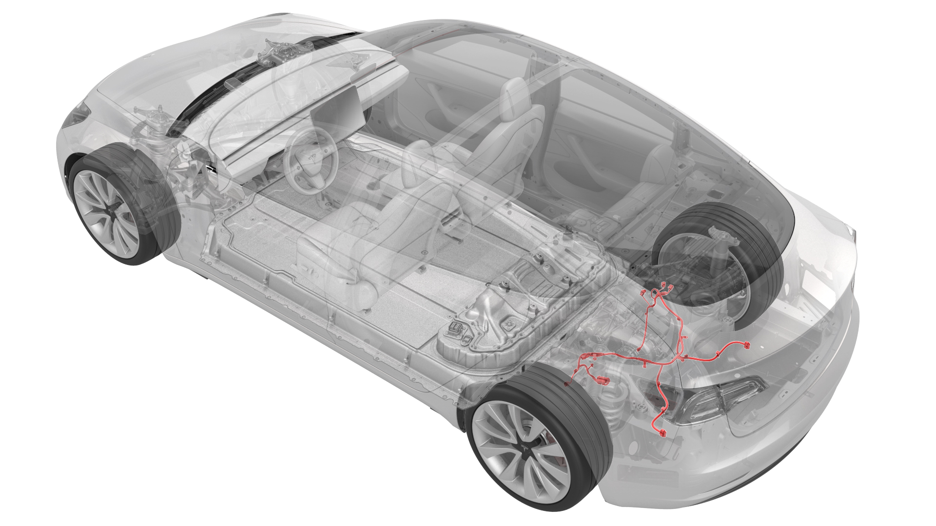
Harness - Subframe - Rear (Remove and Replace)
 Correction code
17102002
0.90
NOTE: Unless otherwise explicitly
stated in the procedure, the above correction code and FRT reflect all of the work
required to perform this procedure, including the linked procedures. Do not stack correction codes unless
explicitly told to do so.
NOTE: See Flat Rate
Times to learn more about FRTs and how they are created.
NOTE: See Personal Protection to make sure wearing proper PPE when
performing the below procedure. NOTE: See Ergonomic Precautions for safe and healthy working
practices.
Correction code
17102002
0.90
NOTE: Unless otherwise explicitly
stated in the procedure, the above correction code and FRT reflect all of the work
required to perform this procedure, including the linked procedures. Do not stack correction codes unless
explicitly told to do so.
NOTE: See Flat Rate
Times to learn more about FRTs and how they are created.
NOTE: See Personal Protection to make sure wearing proper PPE when
performing the below procedure. NOTE: See Ergonomic Precautions for safe and healthy working
practices.
- 2025-04-02: Split the procedure into "Remove" and "Install" sections for clarity purposes.
Remove
-
Raise and support vehicle
NoteEnsure vehicle is not charging before lifting it off the ground
- Lower LH front window
-
Open all four doors
NoteIf vehicle is being powered down, Latch rear doors to prevent accidental closure
-
Move LH front seat forward
-
Move RH front seat forward
-
Remove 2nd row seat cushion and disconnect harness
Note2x tabs, 2x connectors, Press tab toward LH side of vehicle on each side to release front edge of seat cushion
- Open hood
-
Power off vehicle from center display
NoteVia Controls > Safety & Security > Vehicle Power > Power Off, Confirm power off at warning dialogue box
-
Remove rear apron
Note12x clips, only store the rear apron visible face upwards
-
Disconnect 12V negative terminal
Note1x nut, 10mm, 6 Nm, Ensure the vehicle is in park, climate control system is off, and vehicle is not charging before disconnecting 12V
-
Remove 12V cap from ancillary bay
Note1x cap
-
Disconnect HVC logic connector and install logic cap
Note1x connector, 1x cap, Release locking tab then push the handle downward to release connector
- Remove all items from pockets and ensure not wearing metal items
-
Inspect HV insulating gloves
NoteCheck gloves for damage prior to each use, Refer to service document TN-15-92-003 R5, for information on inspecting HV gloves, https://service.tesla.com/docs/ServiceBulletins/External/TN/TN-15-92-003_High_Voltage_Awareness_Care_Points_R5.pdf
-
Put on HV insulating gloves and leather over gloves
NoteMake sure to wear Electrical Protective Gloves any time Hioki tester is used
-
Remove bolts securing ancillary bay probe lid cover to ancillary bay cover
Note2x bolts, E10 5-Lobe, 6 Nm, Discard after removal
-
Remove ancillary bay probe lid cover from the ancillary bay cover
-
Verify no high voltage
NoteMake sure to wear PPE (HV gloves, safety glasses) when working on high voltage component, Measure B+ to Ground, B- to Ground, B+ to B-, If voltage is greater than 10V, Pack contactors are not open or welded, Stop work and reach out to Service Engineering
-
Inspect ancillary bay probe lid cover gasket then position onto the ancillary bay cover
NoteConfirm no visual damage present,Good to reuse seal
-
Install bolts securing ancillary bay probe lid cover to ancillary bay cover
Note2x bolts, E10 5-Lobe, 6 Nm, Install new fasteners
-
Raise vehicle fully and lower lift onto locks
NoteSet vehicle to comfortable working height, Make sure there's an audible click of the locks on both sides before lowering, otherwise vehicle may tilt to the side, Verify doors are clear of surrounding objects
-
Remove mid aero shield
Note13x bolts, 10mm, 5 Nm
-
Remove bolts securing the rear diffuser to body
Note6x bolts, 10mm, 4 Nm, 2x fastener covers
-
Remove outer bolts securing rear diffuser to rear fascia assembly
Note4x bolts, 10mm, 3 Nm
-
Remove lower clips securing LH rear wheel liner
Note3x push clips
-
Remove lower clips securing the RH rear wheel liner
Note3x push clips
-
Remove bolts securing rear lower fascia to rear fascia diffuser
Note2x bolts, 10mm, 3 Nm
-
Release tabs securing rear diffuser to rear fascia and remove from vehicle
Note10x tabs, Start from one side and work your way across while releasing tabs
-
Remove LH rear wheel speed sensor harness connector clip from subframe
Note1x clip
-
Disconnect LH rear wheel speed harness
Note1x connector, Release locking tab, Use mechanical hands to hold the connector end on subframe harness side
-
Remove RH rear wheel speed sensor harness connector clip from subframe
Note1x clip
-
Disconnect RH rear wheel speed sensor connector
Note1x connector
-
Disconnect harness from ride height level sensor
Note1x connector, Press the locking tab on the right side of the connector and pull down to release
-
Remove the harness clip to the ride height level sensor
Note1x clip
-
Disconnect RH side 12V subframe harness connector
Note1x connector, Release locking tab
-
Remove RH side 12V subframe harness clip from body
Note1x barrel clip
-
Disconnect LH side 12V subframe harness connector
Note1x connector
-
Remove LH side 12V subframe harness clip from body
Note1x barrel clip
-
Release clips securing subframe harness to bottom rear of subframe
Note2x clips
-
Disconnect oil pump connector
Note1x connector
-
Disconnect resolver connector from drive unit
Note1x connector, 2x clips, Release locking tab
-
Disconnect RDU 12V connector
Note1x connector, Release locking tab then push the handle downward to release connector
-
Remove RDU 12V harness clip
Note1x clip
-
Loosen the clip that secures the inverter and coolant hose to the RDU
Note3x clips
-
Release clips securing subframe harness to top of rear subframe
Note4x clips
-
Release clips securing subframe harness to left and right of subframe
Note2x clips, There is enough space to use the clip prytool to release the clips
-
Remove the harness from the subframe
NoteTake out the harness from the gap between the RDU and the subframe, and take out the harness from left to right
Install
-
Install the harness to the subframe
NotePass the new harness through the gap between the subframe and RDU from right to left, and fix the harness on the subframe, taking care not to damage the harness
-
Install rear subframe harness into position and secure clips along left and right of subframe
Note2x clips
-
Install clips securing subframe harness to top of rear subframe
Note4x clips
-
Secure the coolant hose to the RDU
Note3x clips
-
Connect LH rear wheel speed sensor
Note1x connector
-
Install harness connector clip to subframe
Note1x clip
-
Connect RH rear wheel speed sensor connector
Note1x connector
-
Install harness connector clip to subframe
Note1x clip
-
Plug in the connector to the ride height level sensor
Note1x connector, 1x locking tab
-
Install the harness clip to the ride height level sensor
Note1x harness clip
-
Install RDU 12V harness clip
Note1x clip
-
Install RDU 12V connector
Note1x connector, Engage locking handle
-
Connect resolver connector to drive unit
Note1x connector, 2x clips, Engage locking tab
-
Connect the oil pump connector
Note1x connector, Engage locking tab
-
Install clips securing subframe harness to bottom rear of subframe
Note2x clips
-
Install LH side 12V subframe harness clip to body
Note1x barrel clip
-
Connect LH side 12V subframe harness connector
Note1x connector
-
Install RH side 12V subframe harness clip to body
Note1x barrel clip
-
Connect RH side 12V subframe harness connector
Note1x connector
-
Install rear diffuser to vehicle then engage tabs securing it to fascia
Note10x tabs
-
Install the bolts securing the rear diffuser to inner rear fascia
Note2x bolts, 10mm, 3 Nm
-
Install outer bolts securing rear diffuser to rear fascia assembly
Note4x bolts, 10mm, 3 Nm
-
Apply Loctite 222 onto rear diffuser bolts and install bolts securing rear diffuser to body
Note6x bolts, 10mm, 4 Nm, 2x fastener covers, Number of bolts may vary on newer vehicles
-
Apply Loctite 222 onto mid aero shield bolts and install mid aero shield
Note13x bolts, 10mm, 5 Nm
-
Lower vehicle until tires are touching the ground
NoteRaise lift off locks, then hold lock release lever to keep locks free while vehicle is lowered
-
Remove logic cap and connect the HVC logic connector
Note1x connector, 1x cap, Align connector then pull the handle to locking position get connector fully seated
-
Install 12V cap to ancillary bay
Note1x cap
-
Connect 2nd row seat cushion harness and install 2nd row seat cushion
Note2x connectors, 2x clips, Insert the seat belt buckles through the holes, Slide rear cushion inward then align front guide tabs to locking tabs, Make sure cushion is fully seated with push & pull test near clips
-
Connect 12V negative terminal
Note1x nut, 10mm, 6 Nm
-
Install cabin intake upper duct assembly
Note3x clips, Older vehicles may be equipped with 4x clips
-
Install rear apron
Note12x clips, If present untuck cut loop label and make sure it is still visible after apron is installed, Later builds may not have label
- Close hood
- Move RH front seat to original position
- Move LH front seat to original position
- Raise LH front window
-
Close all four doors
NoteUnlatch rear doors before closing
- Remove lift arms from below vehicle