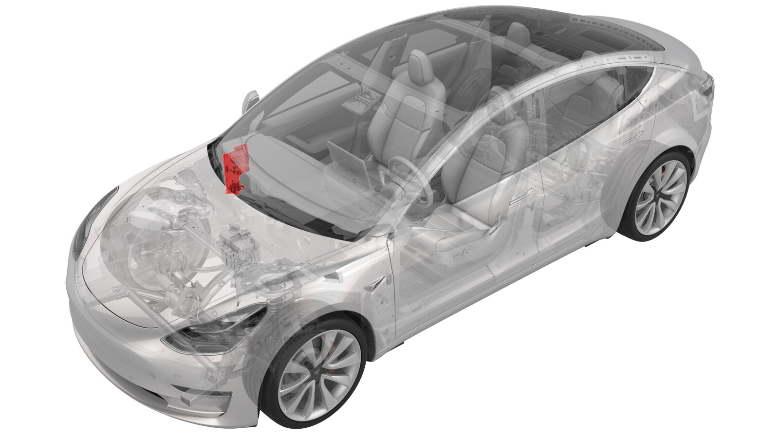
Module - Body Controller - RH (Remove and Replace)
 Correction code
17152202
1.14
NOTE: Unless otherwise explicitly
stated in the procedure, the above correction code and FRT reflect all of the work
required to perform this procedure, including the linked procedures. Do not stack correction codes unless
explicitly told to do so.
NOTE: See Flat Rate
Times to learn more about FRTs and how they are created.
NOTE: See Personal Protection to make sure wearing proper PPE when
performing the below procedure. NOTE: See Ergonomic Precautions for safe and healthy working
practices.
Correction code
17152202
1.14
NOTE: Unless otherwise explicitly
stated in the procedure, the above correction code and FRT reflect all of the work
required to perform this procedure, including the linked procedures. Do not stack correction codes unless
explicitly told to do so.
NOTE: See Flat Rate
Times to learn more about FRTs and how they are created.
NOTE: See Personal Protection to make sure wearing proper PPE when
performing the below procedure. NOTE: See Ergonomic Precautions for safe and healthy working
practices.
- 2025-03-10: Updated post-replacement routine.
Torque Specifications
| Description | Torque Value | Recommended Tools | Reuse/Replace | Notes |
|---|---|---|---|---|
| Nuts (x2) that attach the RH side carpet locator bracket to the vehicle |
 2.5 Nm (1.8 lbs-ft) |
|
Reuse | |
| Nuts that attach the electrical wiring to the RH body controller module |
|
Replace | ||
| Nut that attaches the DCDC positive cable from the RH body controller module |
8.5 Nm (6.3 lbs-ft) |
|
||
| Nut that attaches the RH body controller module to the body |
|
Replace |
Remove
- On the touchscreen, power off the climate control system, and wait at least 30 seconds for the climate control system to completely shut down.
- Remove the 2nd row lower seat cushion. See Seat Cushion - Lower - 2nd Row (Remove and Replace).
-
Remove the rear underhood apron. See Underhood Apron - Rear (Remove and Replace).
CAUTIONDo not proceed until the climate control system has been powered off for at least 30 seconds. Do not disconnect 12V power while the climate control system is operational.
- Disconnect 12V power. See 12V/LV Power (Disconnect and Connect).
- Remove the LH instrument panel end cap. See End Cap - Instrument Panel - LH (Remove and Replace).
- Remove the LH air wave end cap. See End Cap - Air Wave - LH (Remove and Replace).
- Repeat steps 5 and 6 for the RH side of the vehicle.
- Remove the main instrument panel decor trim. See Decor Trim - Instrument Panel - Main (Remove and Replace).
- Remove the RH middle A-pillar trim. See Trim - A-Pillar - Middle - LH (Remove and Replace).
- Remove the RH lower A-pillar trim. See Trim - A-Pillar - Lower - LH (Remove and Replace).
- Remove the passenger footwell cover. See Cover - Footwell - Passenger (LHD) (Remove and Replace).
- Remove the front passenger knee airbag. See Airbag - Knee - Front Passenger (Remove and Replace).
- Remove the glove box. See Glove Box - With Knee Airbags (Non-Heat Pump) (Remove and Replace).
- Remove the RH front floor mat.
- Remove the RH center console side panel carpet. See Side Panel - Center Console - LH (Remove and Replace).
-
Release the clips that attach the RH front carpet to the RH footwell.
- Fold back the RH front carpet.
-
Remove the nuts that attach the RH side carpet locator bracket to the vehicle, and then remove the RH side carpet locator bracket from the vehicle.
TIpUse of the following tool(s) is recommended:
- 10 mm socket
NoteSome vehicles may be equipped with push clips instead. -
Disconnect the electrical connectors from the RH body controller module.
-
Release the lock, and then disconnect the RH front door electrical connector from the RH body controller module.
-
Release the connector lock, and then disconnect the front passenger seat electrical connector from the RH body controller module.
-
Disconnect the instrument panel harness coaxial cable from the RH body controller module.
-
Disconnect the instrument panel electrical connector from the RH body controller module.
-
Disconnect the HVAC electrical connector from the RH body controller module.
-
Disconnect the front harness connector from the RH body controller module.
-
Release the clip that attaches the inline electrical connector to the RH body controller module, and then disconnect the electrical connector.
-
Remove and discard the nuts that attach the electrical wiring to the RH body controller module, and remove the electrical wiring from the RH body controller module.
TIpUse of the following tool(s) is recommended:
- 10 mm deep socket
-
Remove the DCDC positive cables (x2) from the RH body controller module.
TIpUse of the following tool(s) is recommended:
- 10 mm 12-point deep socket
- Release the electrical harness clips (x2) from underneath the IP carrier.
-
Release the lock, and then disconnect the body 2 electrical connector from the RH body controller module.
-
Release the lock, and then disconnect the body 1 electrical connector from the RH body controller module.
CAUTIONTo avoid damage, carefully remove the body 1 electrical connector because the lock may get hung up on the IP carrier.
-
Release the lock, and then disconnect the body 3 electrical connector from the RH body controller module.
-
Disconnect the 3 inline electrical connectors at the RH lower A-pillar area.
-
Release the clip that attaches the electrical harness to the RH lower A-pillar area.
-
Release the clips that attach the RH body electrical harness to the RH body controller module.
- Move the RH body harness away from the RH body controller module.
-
Release the clip that attaches the wiring harness to the RH body controller module.
-
Remove and discard the nut that attaches the RH body controller module to the body.
TIpUse of the following tool(s) is recommended:
- 10 mm socket
-
Slide the RH body controller upwards to release the W-clip, then move the RH body controller out from underneath the instrument panel, and then remove the RH body controller from the vehicle.
-
If the RH body controller module has a shroud installed, release the clips that attach the shroud to the module.
NoteA shroud should be installed on the new body controller module even if one was not present during removal.
Install
-
Position the shroud by itself in position on the vehicle.
CAUTIONA shroud should be installed on the body controller module even if one was not present during removal.NotePosition the shroud vertical and move it up above the computer, and then pivot the lower edge so that the shroud sits horizontally.
-
Maneuver the RH body controller module into position under the IP carrier, and then install the 2 clips that attach the shroud to the module.
NoteMake sure that both clips are fully seated.
- Align the W-clip with the body cutout, and then slide down to attach the RH body controller to the body.
-
Install new nut that attaches the RH body controller module to the vehicle.
TIp
- 10 mm socket
-
Install the clip that attaches the wiring harness to the RH body controller.
-
Move the RH body harness towards the right side of the RH body controller, and then install attach the harness clips (x4) to the RH body controller.
-
Install the clip that attaches the RH body harness at the lower A-pillar area.
- Connect the wiring harnesses at the RH lower A-pillar clip.
-
Connect the body 3 electrical connector onto the RH body controller module.
NoteMake sure that the body 3 electrical connector lock is fully engaged.
-
Connect the body 1 electrical connector onto the RH body controller module.
NoteMake sure that the body 1 electrical connector lock is fully engaged.
-
Connect the body 2 electrical connector onto the RH body controller module.
NoteMake sure that the body 2 electrical connector lock is fully engaged.
- Install the harness clips (x2) onto the lower IP carrier.
-
Install the DCDC positive cables onto the RH body controller module.8.5 Nm (6.3 lbs-ft)TIpUse of the following tool(s) is recommended:
- 10 mm 12-point deep socket
-
Install new nuts (x2) that attach the positive cables onto the RH body controller module.
-
Connect the inline electrical connector, and then attach it to the RH body controller module.
-
Connect the front wiring harness electrical connector onto the RH body controller module.
-
Connect the HVAC electrical connector onto the RH body controller module.
-
Connect the instrument panel electrical connector onto the RH body controller module.
-
Connect the instrument panel harness coaxial cable onto the RH body controller module.
-
Connect the front passenger seat electrical connector onto the RH body controller module.
NoteMake sure that the front passenger seat electrical connector lock is fully engaged.
-
Connect the RH front door electrical connector onto the RH body controller module.
NoteMake sure that the RH front door electrical connector lock is fully engaged.
-
Connect the RH front door wiring connectors onto the RH body controller module.
-
Install the nuts that attach the RH carpet locator bracket onto the vehicle.2.5 Nm (1.8 lbs-ft)
- Fold the RH front carpet back to its original position.
-
Install the clips that attach the RH front carpet to the footwell area.
- Install the RH center console side panel carpet. See Side Panel - Center Console - LH (Remove and Replace).
- Install the RH front floor mat.
- Install the glove box. See Glove Box - With Knee Airbags (Non-Heat Pump) (Remove and Replace).
- Install the front passenger knee airbag. See Airbag - Knee - Front Passenger (Remove and Replace).
- Install the passenger footwell cover. See Cover - Footwell - Passenger (LHD) (Remove and Replace).
- Install the RH lower A-pillar trim. See Trim - A-Pillar - Lower - LH (Remove and Replace).
- Install the RH middle A-pillar trim. See Trim - A-Pillar - Middle - LH (Remove and Replace).
- Install the main instrument panel decor trim. See Decor Trim - Instrument Panel - Main (Remove and Replace).
- Install the RH air wave end cap. See End Cap - Air Wave - LH (Remove and Replace).
- Install the RH instrument panel end cap. See End Cap - Instrument Panel - LH (Remove and Replace).
- Install the LH air wave end cap. See End Cap - Air Wave - LH (Remove and Replace).
- Install the LH air wave end cap. See End Cap - Air Wave - LH (Remove and Replace).
-
Connect 12V power. See 12V/LV Power (Disconnect and Connect).
CAUTIONDo not power on the climate control system until this procedure has been fully completed.
- Install the rear underhood apron. See Underhood Apron - Rear (Remove and Replace).
- Install the 2nd row lower seat cushion. See Seat Cushion - Lower - 2nd Row (Remove and Replace).
- Reinstall the vehicle firmware. See Software Reinstall - Touchscreen.
-
Perform the following
routine using Service Mode or Toolbox (see 0005 - Service Modes):
PROC_CONTROLLER_RIGHT_POST-REPLACEMENT-PROCEDUREvia Service Mode Plus:
- low-voltage ➜ Right Controller Post Replacement ➜ Right Controller Post Replacement Procedure
- mid-voltage ➜ Right Controller Post Replacement ➜ Right Controller Post Replacement Procedure
NoteKeep the front passenger seat clear of any objects during calibration.