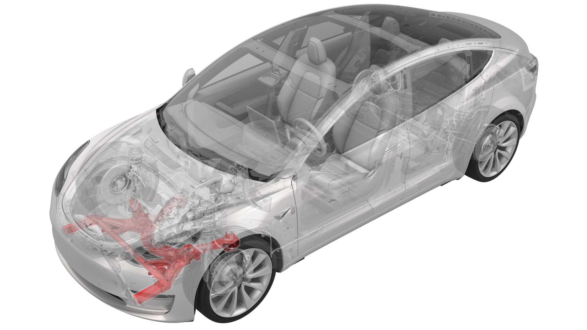
Subframe Assembly - Front (Dual Motor) (Remove and Replace)
 Correction code
30010312
3.90
NOTE: Unless otherwise explicitly
stated in the procedure, the above correction code and FRT reflect all of the work
required to perform this procedure, including the linked procedures. Do not stack correction codes unless
explicitly told to do so.
NOTE: See Flat Rate
Times to learn more about FRTs and how they are created. To provide feedback on
FRT values, email ServiceManualFeedback@tesla.com.
NOTE: See Personal Protection to make sure wearing proper PPE when
performing the below procedure. See Ergonomic Precautions for safe and healthy working practices.
- 1498673-00-A KIT, CABLE AXLE REMOVER, MS/MX/M3
- 1099645-00-C Fixture, Subframe, Model 3
- 1066521-00-A OTC Lift, 1,650LB Powertrain Table
- 1130279-00-A Lifting Sling, Drive Unit, Model 3 (NA, APAC)
- 1130279-01-A Lifting Sling, Drive Unit, Model 3 (EMEA)
Remove
- Remove the front subframe assembly from the vehicle. See Subframe Assembly - Front (Dual Motor) (Remove and Install).
- Remove the steering rack. See Steering Rack (Dual Motor) (LHD) (Remove and Replace).
-
With an assistant, remove and discard the nuts that attach the front stabilizer bar to the front subframe, and then remove the stabilizer bar from the subframe.
-
Remove the bolts that attach LH and RH crash can brackets to the front subframe, and then set the crash can brackets aside.
-
Position the axle remover cable around the inner joint of the LH front drive unit halfshaft, and then use a cable tie to hold the axle remover cable in position.
Figure 1. Axle removed from drive unit for demonstration purposes - Hook the axle remover slide hammer on the 2 axle remover cable loops, and then use the slide hammer to remove the halfshaft from the drive unit.
- Repeat steps 5 to 6 on the RH front drive unit halfshaft.
-
Release the locking tab, and then push the handle downward to disconnect the front drive unit inverter logic connector.
-
Release the red locking tab, and then press down on the tab to disconnect the resolver logic connector.
-
Release the grey locking tab, and then press down on the tab to disconnect the oil pump connector.
-
Release the clip that attaches the front drive unit harness to the front drive unit motor.
-
Release the clips that attach the front drive unit harness to the front subframe.
Figure 2. Other assemblies hidden for clarity -
Release the clips that attach the front drive unit harness to the front drive unit inverter.
-
Remove the front drive unit harness from the front subframe.
- Position the subframe assembly under the gantry.
- Install the drive unit sling onto the gantry hook.
-
Install the drive unit sling hooks onto the front drive unit.
Figure 3. Front drive unit sling hook locations - Slightly raise the gantry hook until the drive unit sling is taut.
-
Remove the bolt that attaches the front drive unit to the front subframe.
-
Lift the front drive unit up and away from the front subframe.
NoteMake sure not to move the rear front drive unit support posts.
- Release the straps that attach the front subframe to the subframe lifting tool.
-
Remove the front subframe from the subframe lifting tool.
Install
-
Position the subframe lifting tool against the front subframe, and then attach the straps (x3) to the subframe.
NoteMake sure to align the two subframe lifting tool guides with the front subframe.
-
Lower the front drive unit onto the front subframe.
NoteMake sure not to move the rear front drive unit support posts from their previous positions.
-
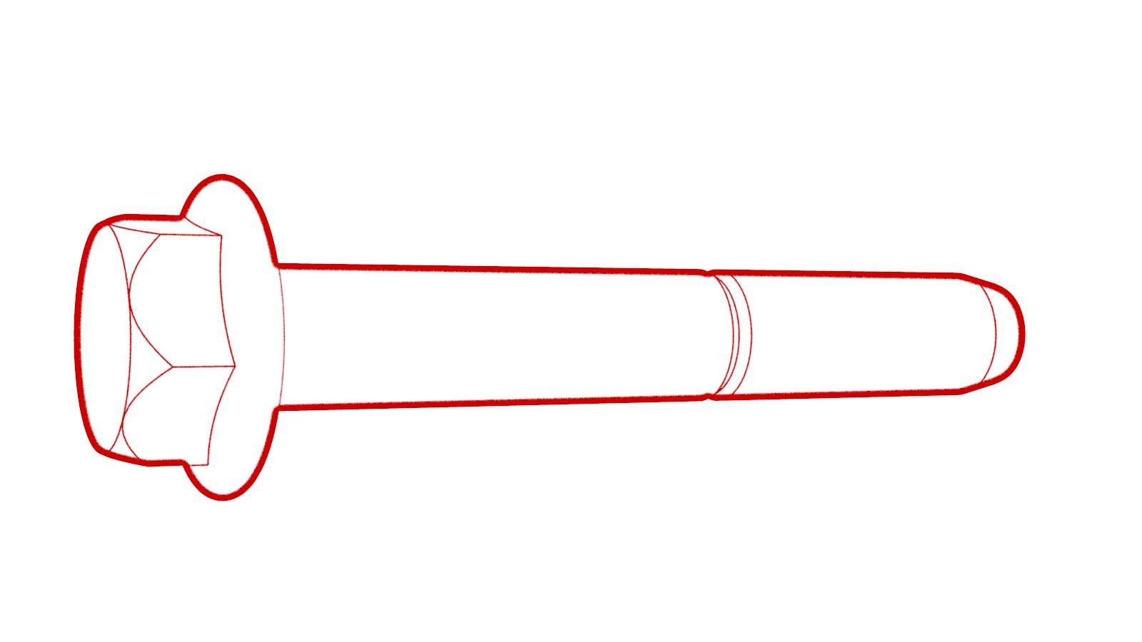
Install the bolt that attaches the front drive unit to the front subframe.
 80 Nm (59.0 lbs-ft)
 - Lower the gantry hook until the drive unit sling is slack.
- Remove the drive unit sling hooks from the front drive unit.
- Remove the drive unit sling from the gantry hook.
- Move the subframe lifting tool to a working area.
-
Position the front drive unit harness on the front subframe, and then install the clips that attach the front drive unit harness to the subframe.
Figure 4. Other assemblies hidden for clarity -
Install the clips that attach the front drive unit harness to the front drive unit inverter.
-
Install the clip that attaches the front drive unit harness to the front drive unit motor.
-
Connect the oil pump connector, and then engage the locking tab.
Important: Perform a push-pull test to verify that the connector is fully attached.
-
Connect the resolver logic connector, and then engage the locking tab.
Important: Perform a push-pull test to verify that the connector is fully attached.
-
Connect the front drive unit inverter logic connector, close the handle, and then engage the locking tab.
Important: Perform a push-pull test to verify that the connector is fully attached.
-
Install the LH and RH front drive unit halfshafts into the front drive unit.
CAUTIONTake care not to damage or displace the oil seals.CAUTIONMake sure that the opening of the snap rings are facing towards the bottom of the drive unit.
-
Verify that the halfshafts are fully seated:
- Carefully push the halfshaft into the drive unit until there is an audible "click" from the halfshaft stub contacting the pinion shaft.
- There will be a slight pulling sensation on the halfshaft as the halfshaft circlip locks into place.
- Pull on the inner halfshaft cup to confirm that the circlip is locked into place. If the halfshaft detaches from the drive unit then reinstall the halfshaft and then test that it is fully seated.
-
Hand-tighten the bolts that attach the LH and RH front subframe crash can brackets to the front subframe.
- Position the front stabilizer bar on the front subframe.
-
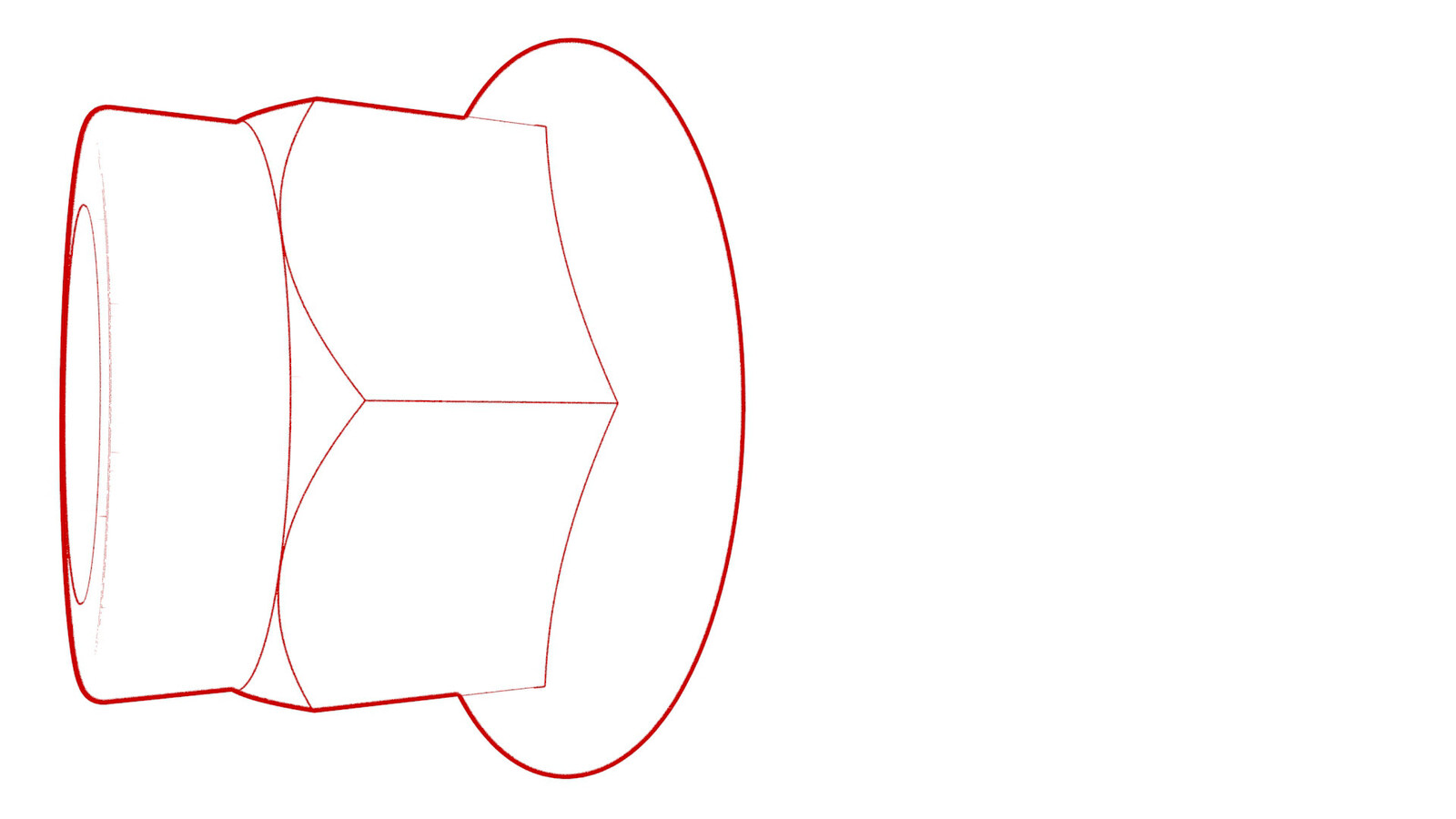
Install new nuts to attach the front stabilizer bar to the front subframe, and then mark each nut with a paint pen.
 35 Nm (25.8 lbs-ft)
 -
Install the steering rack. See Steering Rack (Dual Motor) (LHD) (Remove and Replace).
CAUTION2nd generation front subframes cannot accommodate 1st generation (discontinued) steering racks. A 2nd generation (currently available) steering rack must be installed.
- Install the front subframe assembly into the vehicle. See Subframe Assembly - Front (Dual Motor) (Remove and Install).
- Refer to the Alignment Requirement tables to determine whether an EPAS alignment check (EC) or four wheel alignment check (AC) is necessary. If performed, add the alignment check/adjust correction code as a separate activity to the SV. See Alignment Requirement - Suspension.