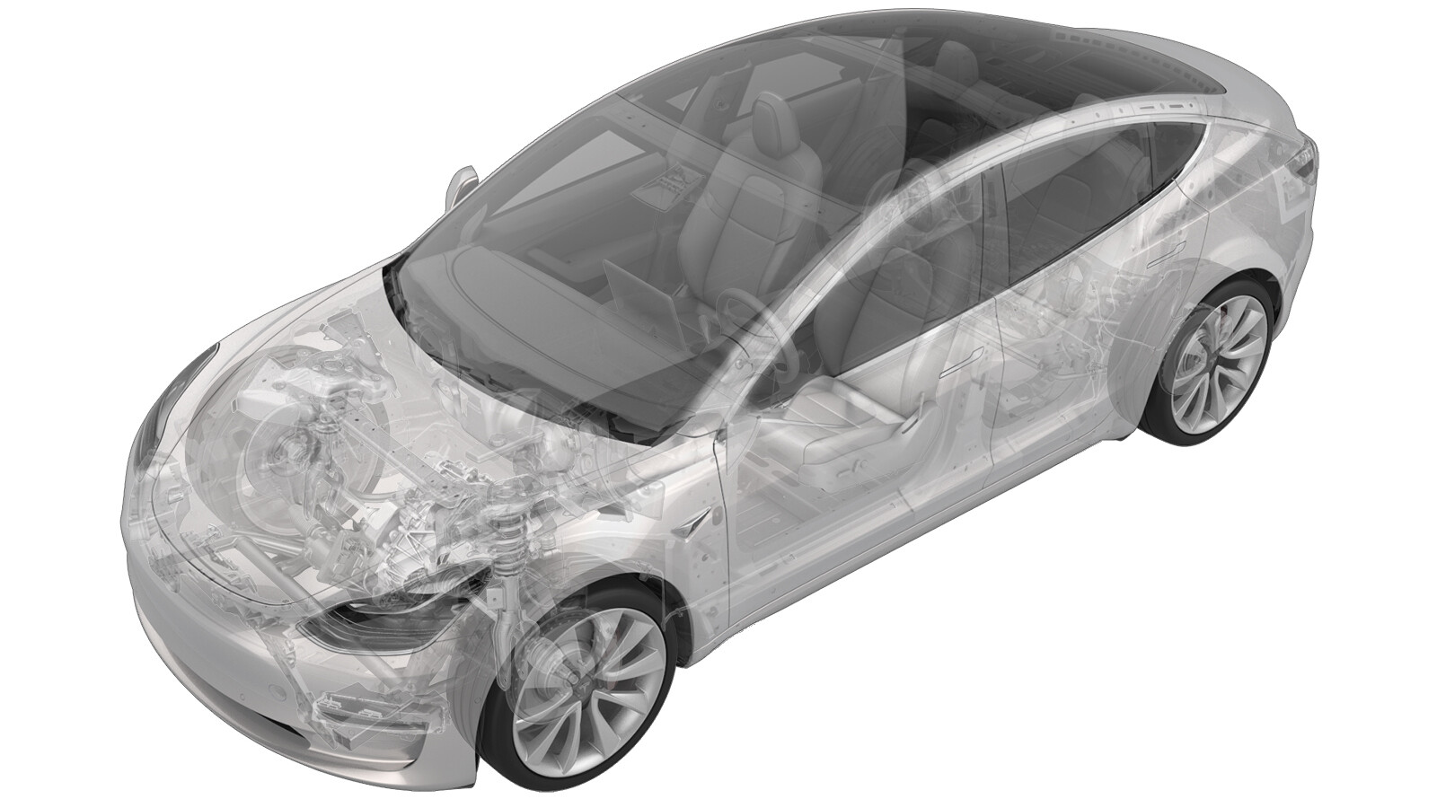
Coolant Pump - Powertrain (Heat Pump) (Remove and Replace)
 Correction code
18308122
0.60
NOTE: Unless otherwise explicitly
stated in the procedure, the above correction code and FRT reflect all of the work
required to perform this procedure, including the linked procedures. Do not stack correction codes unless
explicitly told to do so.
NOTE: See Flat Rate
Times to learn more about FRTs and how they are created. To provide feedback on
FRT values, email ServiceManualFeedback@tesla.com.
NOTE: See Personal Protection to make sure wearing proper PPE when
performing the below procedure. See Ergonomic Precautions for safe and healthy working practices.
- 2025-12-01: Updated images and fixed minor errors.
- 2025-07-09: Add step to change the coolant pump configuration.
- 2024-08-07: Changed instruction for lubrication of O-rings to use Silicone lubricant instead of using silaramic grease.
- 2024-03-04: Updated the routines.
Torque Specifications
| Description | Torque Value | Recommended Tools | Reuse/Replace | Notes |
|---|---|---|---|---|
| Bolts that attach the powertrain coolant pump to the supermanifold |
 1.8 Nm (1.3 lbs-ft) |
|
Reuse |
Remove
- Open the LH front door and fully lower the LH front window.
- Place the vehicle in Service Mode. See Service Mode.
- Remove the cabin intake duct. See Duct - Upper - Cabin Intake (Remove and Replace).
- Remove the fresh intake duct. See Duct - Fresh Intake (Remove and Replace).
- Unlock the vehicle gateway. See Gateway (Unlock).
- On the touchscreen, touch and select Run, and allow the routine to complete.
- Disconnect 12V power. See 12V/LV Power (Disconnect and Connect).
-
Place an absorbent material
underneath the coolant pump.
NoteMake sure the material covers the front drive unit 12V connector, steering rack, and is positioned to catch fluid from the heat exchanger coolant outlet.
-
Release the locking tab, and
then disconnect the electrical harness from the powertrain coolant pump
connector.
CAUTIONDO NOT push down on the red locking tab. Pull the tab away from the connector until the connector is unlocked, and then continue pulling the main body of the connector to fully disconnect it.
-
Remove the bolts (x4) that
attach the powertrain coolant pump to the supermanifold, and then remove the
pump from the supermanifold.
CAUTIONMake sure the inner and outer O-rings are removed with the coolant pump.TIpUse of the following tool(s) is recommended:
- T20 socket
Install
- Remove and discard any o-rings or debris in the supermanifold where the coolant pump will install.
- Make sure that new o-rings are installed onto the new coolant pump.
- Lubricate the o-rings with Silicone lubricant.
-
Position the outlet of the coolant
pump in the up position, and then insert the coolant pump into the supermanifold.
CAUTIONMake sure that the coolant pump is fully seated in the supermanifold.
-
Hand-tighten the bolts (x4) to attach
the coolant pump to the supermanifold.
-
Tighten the coolant pump bolts (x4) in
a cross-pattern.
 1.8 Nm (1.3 lbs-ft)TIpUse of the following tool(s) is recommended:
- T20 socket
-
Connect the electrical
harness to the coolant pump connector, and then engage the locking
tab.
CAUTIONPush the red locking tab towards the connector to engage the locking mechanism. DO NOT push down or pull up on the red locking tab.
- Remove the coolant drain material from under the vehicle.
- Install the fresh intake duct. See Duct - Fresh Intake (Remove and Replace).
- Perform a cooling system vacuum refill. See Cooling System (Vacuum Refill).
- Connect 12V/LV power. See 12V/LV Power (Disconnect and Connect).
- Unlock the vehicle gateway. See Gateway (Unlock).
- On the touchscreen, tap the Service Mode "wrench" (at the bottom of the touchscreen UI), and then tap , and allow the routine to complete.
- Place the vehicle in Service Mode Plus. See Service Mode Plus.
- Tap to inspect the current coolant pump configuration. If the configuration is not DUAL_MIX, change it to DUAL_MIX.
- Tap , and close once the routine is passed.
- Tap , and close once the routine is passed.
- Inspect the coolant level and make sure the fluid level is at the Max line.
- Install the cabin intake duct. See Duct - Upper - Cabin Intake (Remove and Replace).
- On the touchscreen, press and hold the Exit Service Mode button to exit Service Mode Plus.