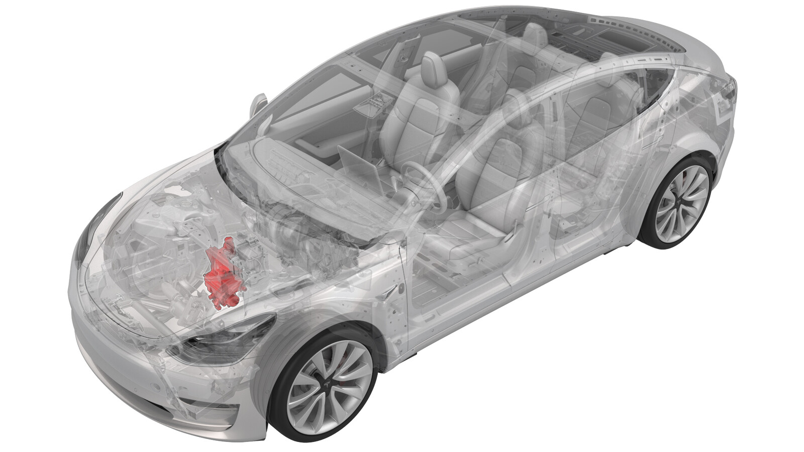
Superbottle (RWD) (Remove and Replace)
 Correction code
18301502
1.08
NOTE: Unless otherwise explicitly
stated in the procedure, the above correction code and FRT reflect all of the work
required to perform this procedure, including the linked procedures. Do not stack correction codes unless
explicitly told to do so.
NOTE: See Flat Rate
Times to learn more about FRTs and how they are created.
NOTE: See Personal Protection to make sure wearing proper PPE when
performing the below procedure. NOTE: See Ergonomic Precautions for safe and healthy working
practices.
Correction code
18301502
1.08
NOTE: Unless otherwise explicitly
stated in the procedure, the above correction code and FRT reflect all of the work
required to perform this procedure, including the linked procedures. Do not stack correction codes unless
explicitly told to do so.
NOTE: See Flat Rate
Times to learn more about FRTs and how they are created.
NOTE: See Personal Protection to make sure wearing proper PPE when
performing the below procedure. NOTE: See Ergonomic Precautions for safe and healthy working
practices.
- 2025-11-19: Deleted reference to Toolbox article 105200.
- 2023-09-06: Removed redundant recharge step.
- 2023-5-2: Information on how to install dual pump in place of single pump
- 2023-4-14: Introduced thermal test routines using the touchscreen.
- 2023-6-7: Updated the Toolbox article link.
Equipment:
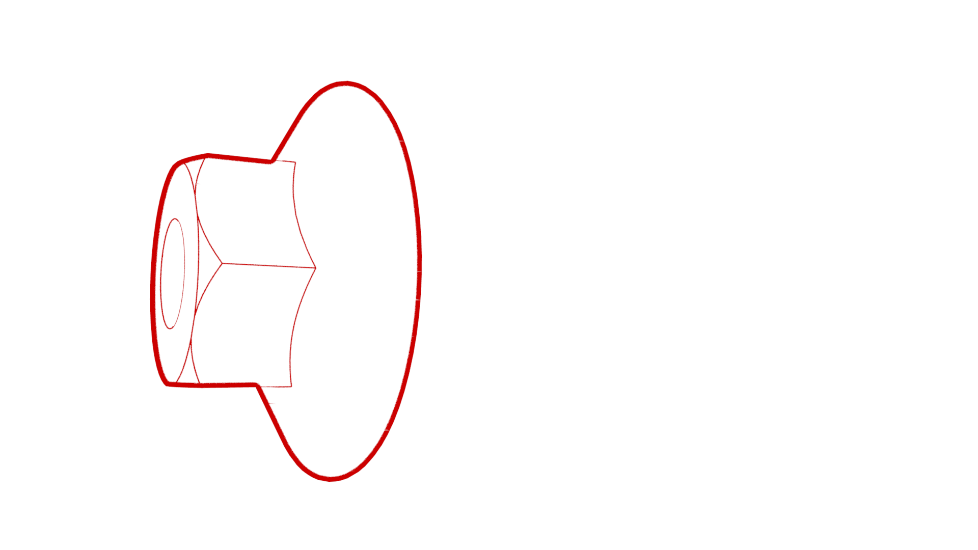
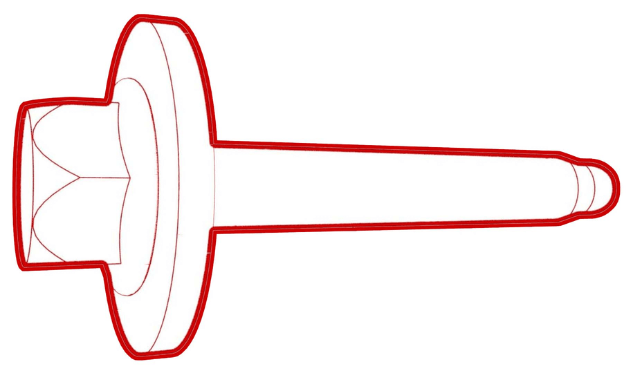
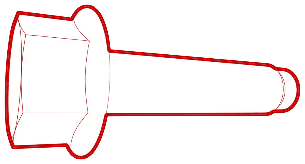
- 1135762-00-A Kit, Svc Plug, Cooling Hose, Model 3
Remove
- Set up the A/C machine and perform a hose flush.
- Put the vehicle in Service Mode. See Service Mode.
- On the touchscreen, touch , select Start Thermal Fill Drain (Coolant & Refrigerant) and then click Run.
- Remove the underhood storage unit. See Underhood Storage Unit (Remove and Replace).
- Disconnect 12V power. See 12V/LV Power (Disconnect and Connect).
-
Recover the A/C refrigerant. See A/C Refrigerant (Recovery and Recharge).
NotePerform the A/C refrigerant recovery procedure while continuing this procedure.
-
Remove the superbottle cap.
- Remove the front aero shield. See Panel - Aero Shield - Front (Remove and Replace).
- Position a coolant drain container under the superbottle.
-
Release the clip and disconnect the powertrain supply hose at the lower LH side of the superbottle.
NoteAllow the coolant to drain from the superbottle.
-
Release the clip and disconnect the battery return hose from the rear left of the superbottle.
-
Release the clip that attaches the battery return hose to the superbottle.
-
Disconnect the electrical harness from the powertrain pump to sill hose coolant temperature sensor connector.
-
Release the clip and disconnect the powertrain pump to sill connector hose from the rear right of the superbottle.
-
Disconnect the superbottle
level sensor connector.
-
Disconnect the 5-way valve
actuator connector.
-
Release the clip that attaches the electrical harness to the lower LH side of the superbottle.
-
Disconnect the electrical harness from the chiller and EXV assembly hose coolant temperature sensor connector.
-
Release the clip that attaches the electrical harness to the chiller and EXV assembly hose, and then remove the electrical harness from the hose.
-
Release the clip that attaches the battery vent hose to the chiller and EXV assembly hose, and then remove the battery vent hose from the chiller and EXV assembly hose.
-
Release the clip and disconnect the coolant hose from the chiller and EXV assembly.
-
Release the clip and disconnect the radiator inlet hose from the front left of the superbottle.
-
Release the clip and disconnect the radiator outlet hose from the front right of the superbottle.
-
Disconnect the HV battery
coolant pump connector.
-
Release the clip that attaches the electrical harness to the suction liquid line.
-
Disconnect the powertrain
coolant pump connector.
-
Disconnect the chiller and
EXV assembly connector.
-
Disconnect the low pressure
transducer connector.
-
Remove the bolt that attaches the suction/liquid line bracket to the shock tower brace, and then separate the bracket from the brace.
-
NoteMake sure that the refrigerant has fully recovered before continuing to the next step.
-
Remove the bolt that attaches the suction/liquid line to the chiller and EXV assembly, and then remove the line from the chiller and EXV assembly.
- Remove and discard the o-rings from the suction/liquid line fitting.
-
Release the clip that attaches the suction/liquid lines to the superbottle.
-
Release the clip that attaches the electrical harness to the superbottle.
-
Remove the bolt that attaches the superbottle to the shock tower brace.
-
Remove the nuts that attach the superbottle to the shock tower brace, and then remove the superbottle from the vehicle.
Install
-
Install the superbottle to the shock tower brace, and then install the nuts that attach the superbottle to the shock tower brace.
 8 Nm (5.9 lbs-ft)
 -
Install the bolt that attaches the superbottle to the shock tower brace.
 8 Nm (5.9 lbs-ft)
 -
Fasten the clip that attaches the electrical harness to the superbottle.
-
Install the clip that attaches the suction/liquid lines to the superbottle.
-
Install new o-rings onto the
suction/liquid line fitting, install the suction/liquid line fitting into
the chiller and EXV assembly, and then install the bolt that attaches the
suction/liquid line to the chiller and EXV assembly.
 22 Nm (16.2 lbs-ft)
 -
After installing the
assembly, recharge the refrigerant. See A/C Refrigerant (Recovery and Recharge).
NotePerform installation of components removed concurrently with refrigerant recharge.
-
Install the suction/liquid line bracket onto the shock tower brace, and then install the bolt that attaches the bracket to the brace.
 5.5 Nm (4.1 lbs-ft)
 -
Connect the electrical harness to the low pressure transducer connector.
-
Connect the electrical harness to the chiller and EXV assembly connector.
-
Connect the electrical harness to the power train coolant pump connector.
-
Fasten the clip that attaches the electrical harness to the liquid suction line.
-
Connect the electrical harness to the HV battery coolant pump connector.
-
Connect the radiator outlet hose to the front right of the superbottle, and then fasten the clip.
-
Connect the radiator inlet hose to the front left of the superbottle, and then fasten the clip.
-
Connect the coolant hose from the chiller and EXV assembly, and then fasten the clip.
-
Install the battery vent hose to the chiller and EXV assembly hose, and then fasten the clip that attaches the battery vent hose to the chiller and EXV assembly hose.
-
Install the electrical
harness to the chiller and EXV assembly hose, and then fasten the clip that
attaches the electrical harness to the hose.
-
Connect the electrical harness to the chiller and EXV assembly hose coolant temperature sensor connector.
-
Fasten the clip that attaches the electrical harness to the lower LH side of the superbottle.
-
Connect the electrical harness to the 5-way valve actuator connector.
-
Connect the electrical harness to the superbottle level sensor connector.
-
Connect the powertrain pump to sill connector hose to the rear right of the superbottle, and then fasten the clip.
-
Connect the electrical harness to the powertrain pump to sill hose coolant temperature sensor connector.
-
Fasten the clip that attaches the battery return hose to the superbottle.
-
Connect the battery return hose to the rear left of the superbottle, and then fasten the clip.
-
Connect the powertrain supply hose at the lower LH side of the superbottle, and then fasten the clip.
- Remove the coolant drain from under the vehicle.
- Install the front aero shield. See Panel - Aero Shield - Front (Remove and Replace).
-
Connect 12V power. See 12V/LV Power (Disconnect and Connect).
NoteDo not install the rear underhood apron at this time.
- On the touchscreen, touch START at "Start Thermal Fill Drain (Coolant and Refrigerant)".
- Perform a cooling system vacuum refill. See Cooling System (Vacuum Refill).
- On the touchscreen, touch START at "Start Coolant Air Purge".
-
Inspect coolant level in superbottle, top off as necessary and then install
the superbottle cap.
NoteFluid level in superbottle should be 5 mm above the MAX line.
- On the touchscreen, touch START at "Test HVAC Performance".
- On the touchscreen, touch , touch START at "Test Thermal Performance", and then touch Run.
- Exit Service Mode. See Service Mode.
- Install the underhood storage unit. See Underhood Storage Unit (Remove and Replace).
- Install the rear underhood apron. See Underhood Apron - Rear (Remove and Replace).