ABS Modulator (Non-Heat Pump) (Remove and Replace)
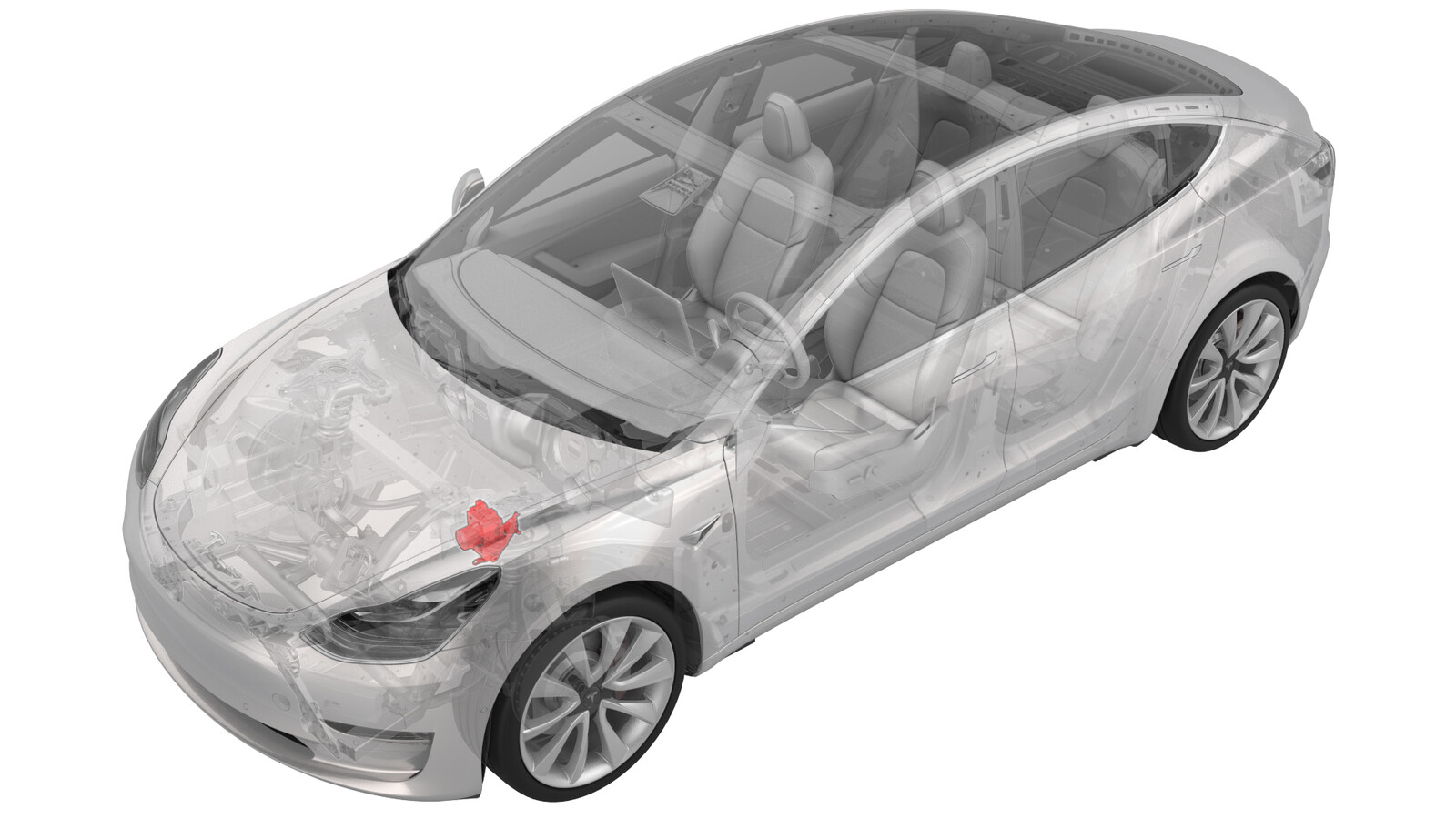 Correction code
33100102
2.34
NOTE: Unless otherwise explicitly
stated in the procedure, the above correction code and FRT reflect all of the work
required to perform this procedure, including the linked procedures. Do not stack correction codes unless
explicitly told to do so.
NOTE: See Flat Rate
Times to learn more about FRTs and how they are created. To provide feedback on
FRT values, email ServiceManualFeedback@tesla.com.
NOTE: See Personal Protection to make sure wearing proper PPE when
performing the below procedure. See Ergonomic Precautions for safe and healthy working practices.
- 2025-04-29: Corrected torque figures for the bolts that attach the shock tower brace to the vehicle.
- 2023-12-05: Updated brake stiffness routine.
- 2023-06-15: Added a video at Step 8 in install part to illustrate how to install the master cylinder brake lines.
Remove
- Raise and support the vehicle. See Raise Vehicle - 2 Post Lift.
- Remove the 2nd row lower seat cushion. See Seat Cushion - Lower - 2nd Row (Remove and Replace).
- Remove the rear underhood apron. See Underhood Apron - Rear (Remove and Replace).
- Disconnect 12V power. See 12V/LV Power (Disconnect and Connect).
- Remove all wheels. See Wheel Assembly (Remove and Install).
- Remove the front aero shield panel. See Panel - Aero Shield - Front (Remove and Replace).
- Lower the vehicle.
- Remove the cabin intake duct. See Duct - Upper - Cabin Intake (Remove and Replace).
- Remove the hood latch cover. See Cover - Hood Latch (Remove and Replace).
- Remove the underhood storage unit. See Underhood Storage Unit (Remove and Replace).
- Remove the 12V auxiliary battery. See 12V/LV Battery (Remove and Replace).
- Remove the 12 battery bracket. See Bracket - 12V Battery (RWD) (Remove and Replace).
-
Remove the bolts that attach
G098 and G099 to the body.
-
Release the white clip that
attaches the main front harness to the body.
-
Release the black clip that
attaches the main front harness to the body.
-
Disconnect the electrical
connector from the ABS modulator.
-
Release the clips that
attach the main front harness near the LH frame rail.
- Place the oil drain under the ABS modulator.
-
Remove the RH front brake
line pipe nut from the ABS modulator.
-
Remove the LH rear brake
line pipe nut from the ABS modulator.
-
Remove the RH rear brake
line pipe nut from the ABS modulator.
-
Remove the LH front brake
line pipe nut from the modulator.
-
Remove the master cylinder
secondary pipe nut from the ABS modulator.
-
Remove the master cylinder
primary pipe nut from the ABS modulator.
-
Release the clip that
attaches the master cylinder brake lines to the 4 tube bundle.
-
Release the clip that
attaches the chiller-to-battery coolant hose to the bracket, and move the
hose aside.
-
Remove the bolts that attach
the ABS modulator to the frame rail.
- Release the tabs (x2) that attach the ABS modulator to the body, slide the ABS modulator towards the 12V battery area, and then remove the ABS modulator from the vehicle.
-
Loosen the nut that attach
the ABS modulator to the bracket, and then pry the ABS modulator from the
bracket.
Install
- Install the ABS modulator into the bracket.
-
Tighten the nuts (x2) that
attach the ABS modulator to the bracket.
 8 Nm (5.9 lbs-ft)
 - Remove the tapes that cover the orifices of the new ABS modulator
- Position the ABS modulator into the vehicle for installation. Align the bracket into the body, and then attach the tabs (x2).
- Move the ABS modulator into position within the vehicle for installation.
-
Install the bolts that
attach the ABS modulator to the LH frame rail.
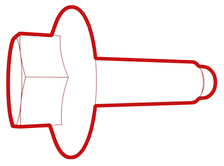 10 Nm (7.4 lbs-ft)
 -
Fasten the clip that
attaches the master cylinder brake lines to the bracket.
-
Install the master cylinder
brake lines to the 4 tube bundle clip.
-
Install the master cylinder
primary pipe nut to the ABS modulator.
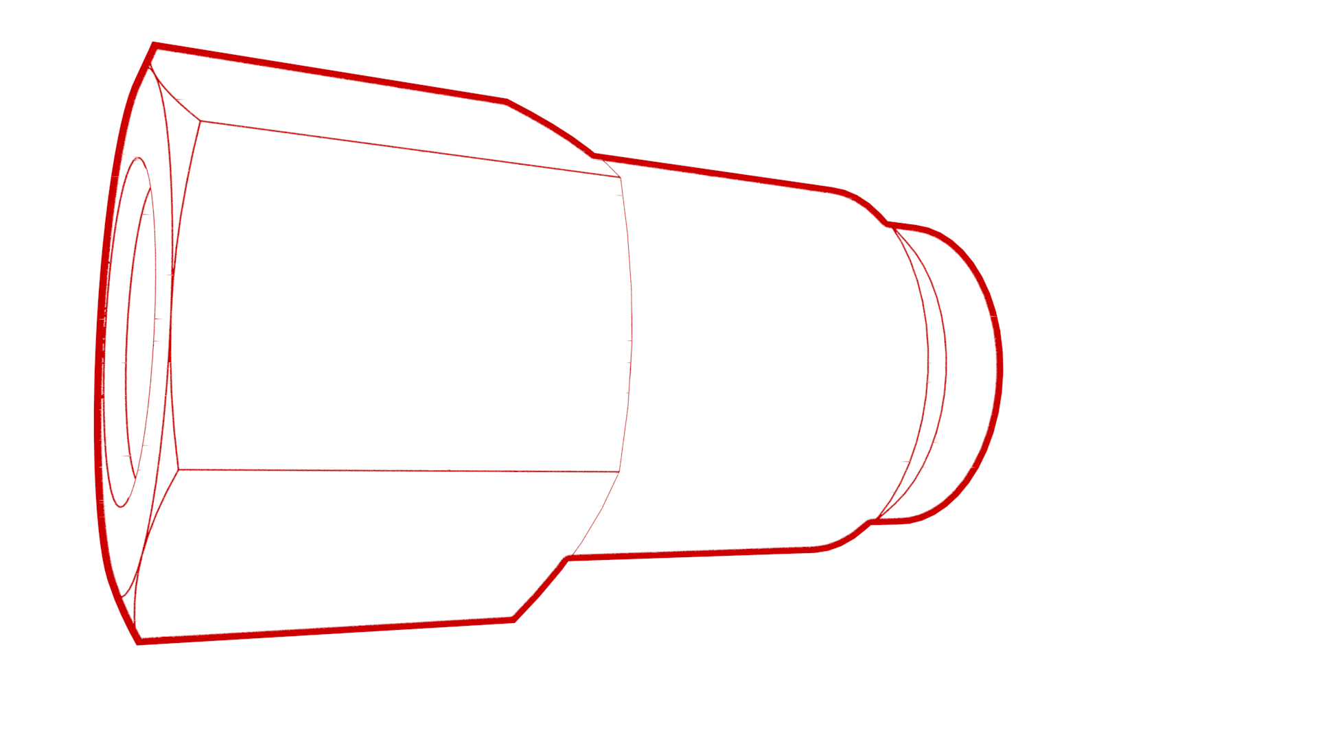 16 Nm (11.8 lbs-ft)
 -
Install the master cylinder
secondary pipe nut to the ABS modulator.
 16 Nm (11.8 lbs-ft)
 -
Install the LH front brake
pipe nut to the ABS modulator.
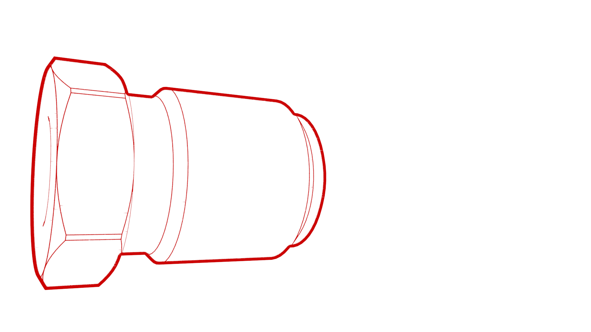 16 Nm (11.8 lbs-ft)
 -
Install the RH rear brake
pipe nut to the ABS modulator.
 16 Nm (11.8 lbs-ft)
 -
Install the LH rear brake
pipe nut to the ABS modulator.
 16 Nm (11.8 lbs-ft)
 -
Install the RH front brake
pipe nut to the ABS modulator.
 16 Nm (11.8 lbs-ft)
 - Remove the oil pan from underneath the vehicle.
-
Install the clips that
attach the main front harness to the LH frame rail area.
-
Connect the electrical
connector to the ABS modulator.
-
Install the black and white
clips (x2) that attach the main front harness to the body.
-
Install the bolts that
attach G098 and G099 to the body.
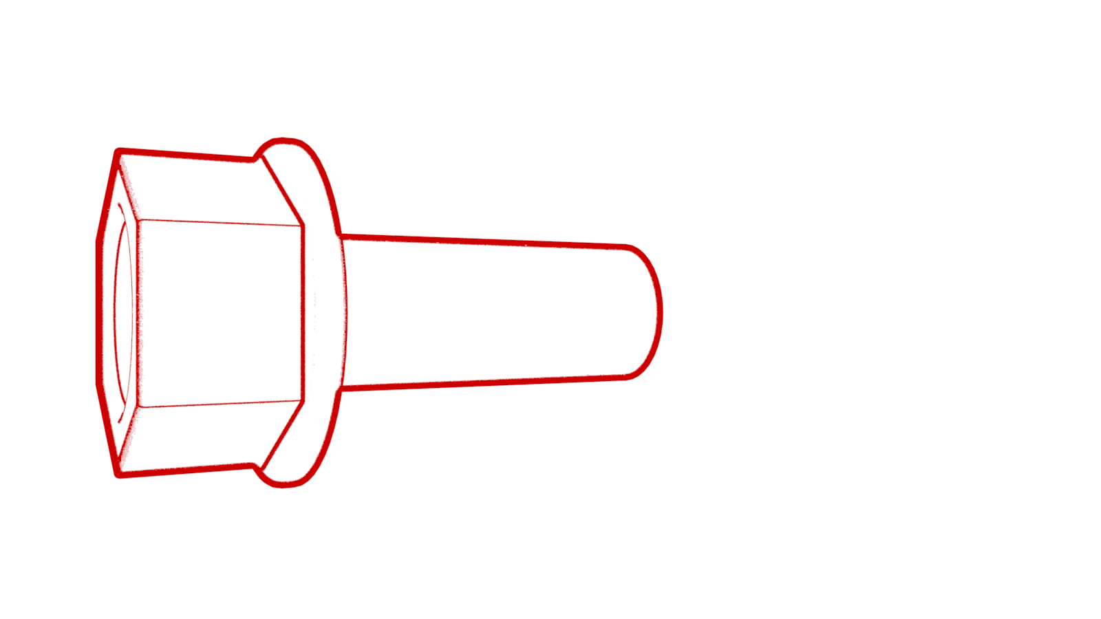 10 Nm (7.4 lbs-ft)
 - Install the 12 battery bracket. See Bracket - 12V Battery (RWD) (Remove and Replace).
- Install the 12V auxiliary battery, but do not connect the negative battery terminal at this time. See 12V/LV Battery (Remove and Replace).
- Install the underhood storage unit. See Underhood Storage Unit (Remove and Replace).
- Install the hood latch cover. See Cover - Hood Latch (Remove and Replace).
- Install the cabin intake duct. See Duct - Upper - Cabin Intake (Remove and Replace).
- Reconnect 12V power. See 12V/LV Power (Disconnect and Connect).
- Install the 2nd row lower seat cushion. See Seat Cushion - Lower - 2nd Row (Remove and Replace).
- Redeploy the vehicle firmware. See Software Reinstall - Toolbox.
- Bleed the entire brake system. See Brake Fluid Bleed/Flush.
-
Using Toolbox 3:
- Install the front aero shield panel. See Panel - Aero Shield - Front (Remove and Replace).
- Install all wheels. See Wheel Assembly (Remove and Install).
- Install the rear underhood apron. See Underhood Apron - Rear (Remove and Replace).
- Remove the vehicle from the lift.
- Perform a road test to make sure that brake pedal feel and brake performance are as expected.