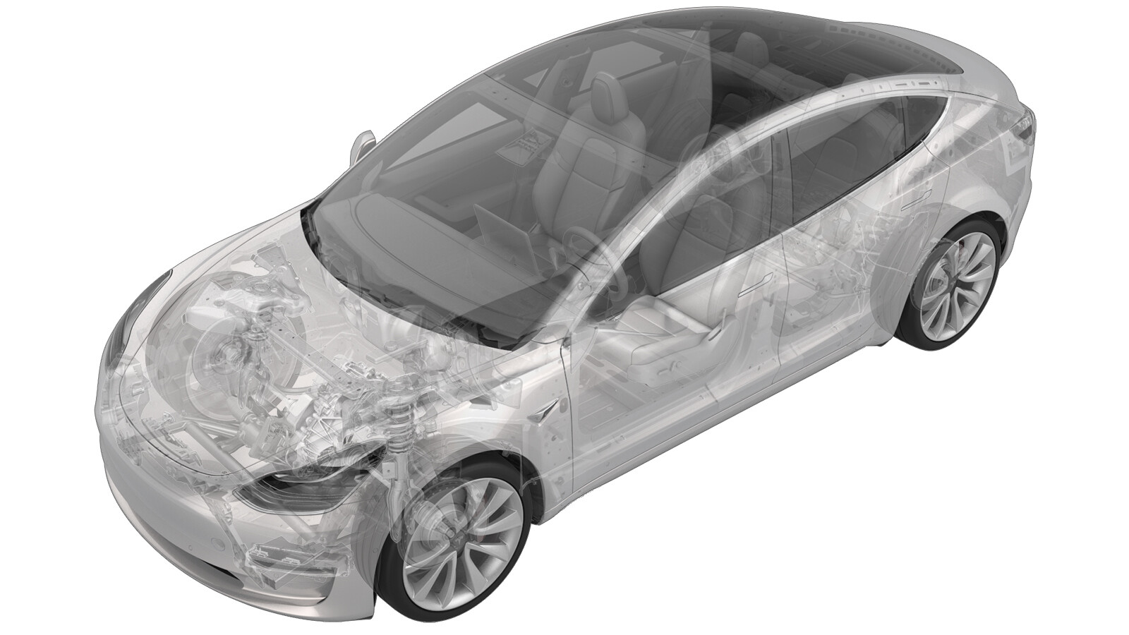
Coolant Pump - HV Battery (Heat Pump) (Remove and Replace)
 Correction code
18308522
0.66
NOTE: Unless otherwise explicitly
stated in the procedure, the above correction code and FRT reflect all of the work
required to perform this procedure, including the linked procedures. Do not stack correction codes unless
explicitly told to do so.
NOTE: See Flat Rate
Times to learn more about FRTs and how they are created.
NOTE: See Personal Protection to make sure wearing proper PPE when
performing the below procedure. NOTE: See Ergonomic Precautions for safe and healthy working
practices.
Correction code
18308522
0.66
NOTE: Unless otherwise explicitly
stated in the procedure, the above correction code and FRT reflect all of the work
required to perform this procedure, including the linked procedures. Do not stack correction codes unless
explicitly told to do so.
NOTE: See Flat Rate
Times to learn more about FRTs and how they are created.
NOTE: See Personal Protection to make sure wearing proper PPE when
performing the below procedure. NOTE: See Ergonomic Precautions for safe and healthy working
practices.
- 2025-07-09: Added steps of configuring the coolant pump type.
- 2024-04-25: Updated the UI routines.
Torque Specifications
| Description | Torque Value | Recommended Tools | Reuse/Replace | Notes |
|---|---|---|---|---|
| Bolts (x4) that attach the HV battery coolant pump to the supermanifold |
 1.8 Nm (1.3 lbs-ft) |
|
Reuse |
Remove
-
Place the vehicle on the 2-post
lift.
TIpEnsure the vehicle is not charging.
- Place the vehicle in Service Mode. See Service Mode.
- Remove the cabin intake duct. See Duct - Upper - Cabin Intake (Remove and Replace).
- Unlock the vehicle gateway. See Gateway (Unlock).
- On the touchscreen, touch and select Run, and allow the routine to complete.
- Disconnect 12V power. See 12V/LV Power (Disconnect and Connect).
- Remove the front aero shield panel. See Panel - Aero Shield - Front (Remove and Replace).
-
Release connector lock, and then
disconnect the HV battery coolant pump electrical connector.
NoteDo not push down on the red tab. Pull the red tab to disengage lock, and then pull again to release the connector.
- Position a coolant drain container underneath the battery coolant pump.
-
Remove the bolts (x4) that attach the
HV battery coolant pump to the the supermanifold.
TIpUse of the following tool(s) is recommended:
- Torx T20 socket
-
Remove the HV battery coolant pump
from the Supermanifold.
NoteMake sure both o-rings (inner purple and outer black) come off with old pump.
Install
- Lubricate both o-rings with silicone o-ring lubricant before installation.
-
Position the HV battery coolant pump
to the supermanifold, and then install and hand-tighten the bolts (x4).
TIpUse of the following tool(s) is recommended:
- Torx T20 socket
NoteTake note of the connector position and install the coolant pump with the connector tab facing up.TIpInstall the upper right bolt with the coolant pump for easier installation.NoteMake sure the coolant pump is fully seated. -
Torque the bolts (x4) that attach the
HV battery coolant pump to the Supermanifold.1.8 Nm (1.3 lbs-ft)TIpUse of the following tool(s) is recommended:
- Torx T20 socket
-
Connect the HV battery coolant pump
electrical connector, and then engage the connector locking tab.
- Remove the coolant drain container from underneath the vehicle.
- Install the front aero shield panel. See Panel - Aero Shield - Front (Remove and Replace).
- Perform a cooling system vacuum refill. See Cooling System (Vacuum Refill).
- Connect 12V power. See 12V/LV Power (Disconnect and Connect).
- Unlock the vehicle gateway. See Gateway (Unlock).
- On the touchscreen, tap the Service Mode "wrench" (at the bottom of the touchscreen UI), and then tap , and allow the routine to complete.
-
Place the vehicle in Service Mode
Plus.
- Enter the last six digits of VIN into the Vehicle Ops mobile app.
- Select vehicle from the list.
-
Swipe to the left, and then select
Enable Service Mode Plus
.
- Tap to inspect the current coolant pump configuration. If the configuration is not DUAL_MIX, change it to DUAL_MIX.
- Tap , and close once the routine is passed.
- Tap , and close once the routine is passed.
-
Inspect the coolant level and top off
as necessary.
NoteEnsure that the coolant is filled to the "Max" line.
- Install the coolant bottle cap.
- Install the cabin intake duct assembly. See Duct - Upper - Cabin Intake (Remove and Replace).
- On the touchscreen, press and hold the Exit Service Mode button to exit Service Mode Plus.