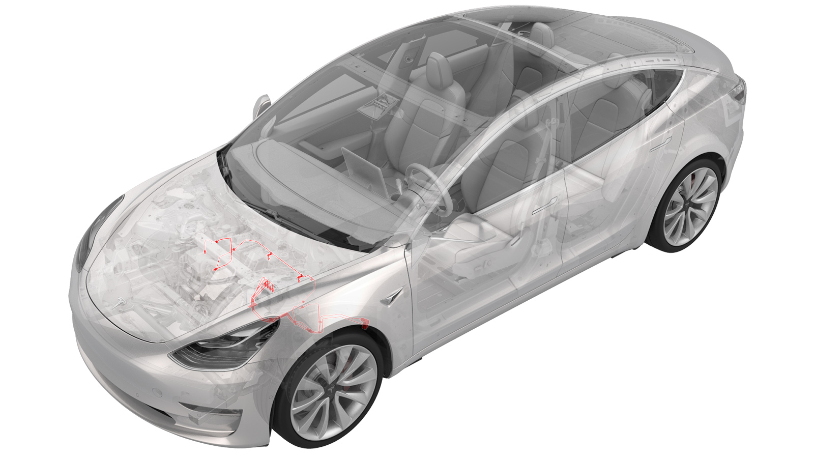
Brake Lines - 4 Tube Bundle - ABS to Wheels (Dual Motor) (Remove and Replace)
 Correction code
330339524.62
NOTE: Unless otherwise explicitly
stated in the procedure, the above correction code and FRT reflect all of the work
required to perform this procedure, including the linked procedures. Do not stack correction codes unless
explicitly told to do so.
NOTE: See Flat Rate
Times to learn more about FRTs and how they are created. To provide feedback on
FRT values, email ServiceManualFeedback@tesla.com.
NOTE: See Personal Protection to make sure wearing proper PPE when
performing the below procedure. See Ergonomic Precautions for safe and healthy working practices.
Brake fluid dissolves paint. Have clean towels and plenty of water standing by to wash spilled brake fluid off painted surfaces.
Dispose of used brake fluid in a manner consistent with local environmental codes.
- Remove the front subframe. See Subframe Assembly - Front (Dual Motor) (Remove and Install).
- Remove the 12V battery bracket. See Bracket - 12V Battery (Dual Motor) (Remove and Replace).
-
Remove the bolts (x2) that attach the ground leads (G098 and G099) to the LH side of the body.
NoteDiscard thread-cutting tri-lobular bolts after removal. If equipped with new bolts (1447438-00-A), the bolts can be reused.
-
Release the white harness clip from the body.
-
Release the black harness clip from the body.
-
Remove the front harness clip from the LH frame rail area.
-
Disconnect the ground connector (G011) from the LH frame rail area.
-
Move the LH side of the front harness aside for access.
-
Disconnect the ABS modulator connector.
NoteDisengage locking tab and pull up on the connector to release.
-
Release the front harness clips (x2) at the LH frame rail area.
- Position the oil drain under the ABS unit.
-
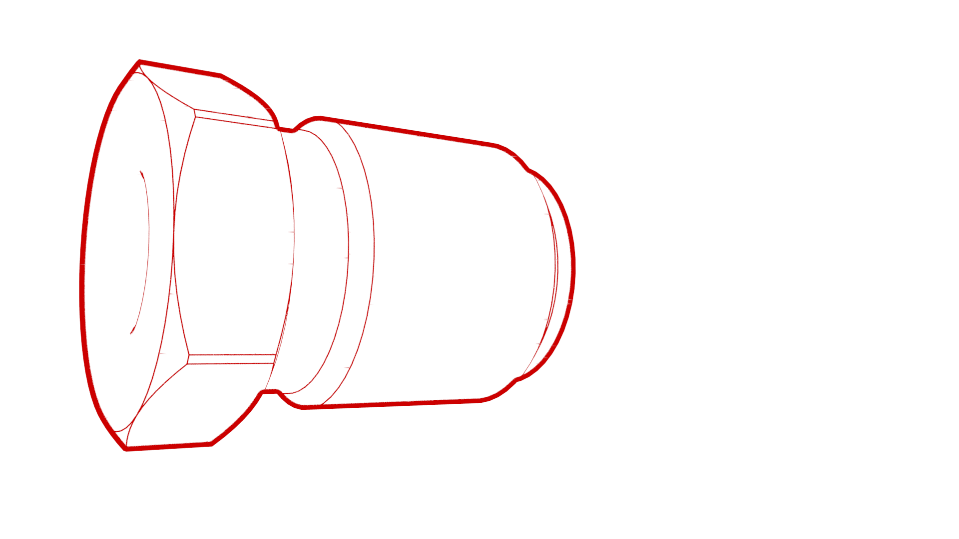
Remove the brake line tube nuts from the ABS unit, and allow the fluid to drain.
-
Remove the front brake line bundle clip at the LH front rail area.
-
Remove the RH front brake line from the front brake line bundle clip at the LH front rail area.
- Remove the oil drain container from underneath the vehicle.
- Partially raise the vehicle.
-
Remove the thermal beam hose clips (x2) from the body.
- Position the oil drain under the front brake line junction block.
-
Remove the brake line tube nuts from the junction block, and allow the fluid to drain.
-
Remove the black clip from the LH front junction block.
-
Release the brake lines from the LH front junction block.
- Position the oil drain under the front LH brake hose.
-
Remove the brake line tube nut from the brake hose at the jounce hose bracket, and allow the fluid to drain.
-
Remove the LH front brake line clip from the body.
- Position the oil drain under the front RH brake hose.
-
Remove the brake line tube nut from the brake hose at the jounce hose bracket, and allow the fluid to drain.
-
Remove the RH front brake line clips (x2) from the body.
- Fully raise the vehicle.
-
Release the coolant hose clip on the LH fender.
-
Remove the front brake line bundle clip from the LH body rail area.
-
Remove the LH front side 3 bundle brake lines from the vehicle.
NoteRoute the front brake line bundle out of steering column area, then route it through LH front wheel liner and front subframe area.
-
Release the clips (x3) that attach the 12V harness to the body.
-
Release the clips (x7) that attach the HV cables to the body.
-
Release the clips (x2) that attach the coolant manifold line from the body.
-
Release the clips (x4) that attach the coolant hoses to the body.
-
Release the clip that attaches the coolant hose to the RH side of the body.
-
Remove the clips (x5) that attach the RH front brake line to the body.
-
Remove the RH front brake line from the vehicle.
NoteRoute the brake line out of steering column area, then move it towards the RH side, and the remove it out between the front subframe area.
Install
- Remove the RH front brake line from the new front 4 tube brake bundle.
-
Position the RH front brake line to vehicle for installation.
NoteRoute the RH front brake line through the front subframe area out toward the RH front wheel liner area, then route it to LH frame rail area.
-
Install the clips (x5) that attach the RH front brake line to the body.
-
Install the clip that attaches the RH side coolant hose to the body.
-
Install the clips (x4) that attach the coolant hoses to the body.
-
Install the clips (x2) that attach the coolant manifold line to the body.
-
Install the clips (x7) that attach the HV cables to the body.
-
Install the clips (x3) that attach the 12V harness to the body.
-
Install the left side 3 tube bundle to the vehicle.
NoteRoute the brake line bundle through the LH front wheel liner and front subframe area, then route it to LH frame rail area.
-
Install the clip that attaches the coolant hose to the LH fender.
-
Install the clip that attaches the front brake line bundle to LH body rail area.
- Partially lower the vehicle.
-
Install the RH front brake line into the brake hose at the jounce hose bracket, and then use a crowfoot extension to install the brake line tube nut into the brake hose.
 16 Nm (11.8 lbs-ft)
 -
Install the RH front brake line clips (2) to the body.
-
Insert the brake line into the brake hose at the jounce hose bracket, and then use a crowfoot extension to install the brake line tube nut into the brake hose.
 16 Nm (11.8 lbs-ft)
 -
Install the clip that attaches the LH front brake line clip to body
Note1x clip
-
Install the brake lines into the LH front junction block.
-
Install the clip that secures the brake lines at the LH front junction block.
-
Use a crowfoot extension to install the brake line tube nuts into the junction block.
 16 Nm (11.8 lbs-ft)
 -
Install the thermal beam hose clips (x2) to the body.
- Lower the vehicle.
-
Install the RH front brake line to front brake line bundle clip at the LH front rail area.
-
Install the front brake line bundle clip at the LH front rail area.
-
Install the master cylinder brake lines to the 4 tube bundle clip.
-
Insert the brake lines into the ABS unit, and then use a crowfoot extension to install the brake line tube nuts into the ABS unit.
 16 Nm (11.8 lbs-ft)
 -
Re-position the LH side of the front harness to the LH frame rail for installation.
-
Install the front harness clips (x2) at the LH frame rail area.
-
Connect the LH frame rail ground connector (G011).
-
Install the front harness clip to the LH frame rail area.
-
Install the white harness clip to the left front fender.
-
Install the black harness clip to the left front fender.
-
Install the bolts (x2) that attach the grounds leads (G098 and G099) to the body (torque 10 Nm).
NoteInstall new bolts if thread-cutting tri-lobular bolts were installed previously. Hand-start bolts at least 6 rotations before applying torque to avoid damaging the weld nut.
-
Install the ABS modulator connector
NoteGently push connector downward, then engage locking tab
- Reinstall the 12V battery bracket. See Bracket - 12V Battery (Dual Motor) (Remove and Replace).
- Install the 12V battery into the vehicle. See 12V/LV Battery (Remove and Replace).
- Install the front subframe. See Subframe Assembly - Front (Dual Motor) (Remove and Install).
- Connect 12V power. See 12V/LV Power (Disconnect and Connect).
- Remove the HVAC plenum outer duct. See Plenum - Inlet - HVAC (Remove and Replace).
- Perform a coolant air purge. See Cooling System (Partial Refill and Bleed).
- Bleed the brakes. See Brake Fluid Bleed/Flush.
- Install the underhood storage unit. See Underhood Storage Unit (Remove and Replace).
- Install the HVAC plenum outer duct. See Plenum - Inlet - HVAC (Remove and Replace).
- Install the rear underhood apron. See Underhood Apron - Rear (Remove and Replace).
- Install the front aero shield. See Panel - Aero Shield - Front (Remove and Replace).
- Install the LH and RH wheel liner. See Wheel Arch Liner - Front - LH (Remove and Replace).
- Install all wheels. See Wheel Assembly (Remove and Install).
- Torque the LH and RH front halfshaft nuts to 300 Nm.
- Perform a 4-wheel alignment check. See Four Wheel Alignment Check.