Compressor (Non-Heat Pump) (Remove and Replace)
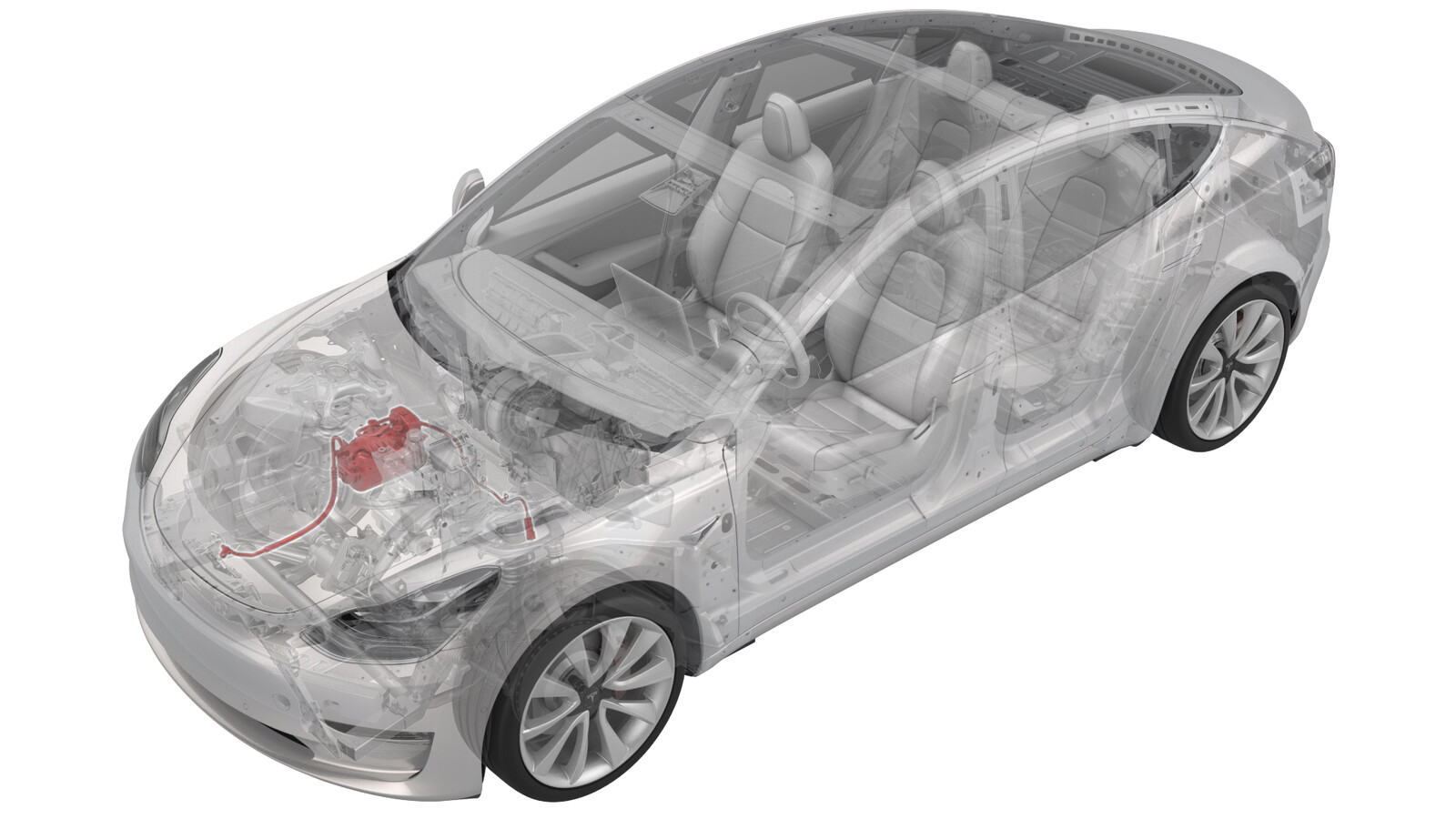 Correction code
18203902
2.22
NOTE: Unless otherwise explicitly
stated in the procedure, the above correction code and FRT reflect all of the work
required to perform this procedure, including the linked procedures. Do not stack correction codes unless
explicitly told to do so.
NOTE: See Flat Rate
Times to learn more about FRTs and how they are created. To provide feedback on
FRT values, email ServiceManualFeedback@tesla.com.
NOTE: See Personal Protection to make sure wearing proper PPE when
performing the below procedure. See Ergonomic Precautions for safe and healthy working practices.
- 2024-11-05: Corrected torque figure for the bolt that attaches the fitting to the chiller and EXV assembly.
Only
technicians who have completed all required certification courses are permitted to
perform this procedure. Tesla recommends third party service provider technicians
undergo equivalent training before performing this procedure. For more information on
Tesla Technician requirements, or descriptions of the subject matter for third parties,
see HV Certification Requirements. Proper personal protective equipment (PPE) and insulating HV
gloves with a minimum rating of class 0 (1000V) must
be worn at all times a high voltage cable, busbar, or fitting is handled. Refer to Tech Note TN-15-92-003, High Voltage Awareness
Care Points
for additional safety
information.
Remove
- Remove the underhood storage unit. See Underhood Storage Unit (Remove and Replace).
- Remove the outer HVAC plenum duct. See Plenum - Inlet - HVAC (Remove and Replace).
-
Recover the A/C refrigerant. See A/C Refrigerant (Recovery and Recharge).
NoteRecover the refrigerant while continuing this procedure.
- Disconnect 12V power. See 12V/LV Power (Disconnect and Connect).
- Perform the vehicle electrical isolation procedure. See Vehicle HV Disablement Procedure.
- Remove the front aero shield. See Panel - Aero Shield - Front (Remove and Replace).
-
Disconnect the compressor HV electrical connector from the HV electrical harness.
-
Release the clips that attach the compressor HV electrical harness to the bulkhead.
-
Disconnect the electrical harness from the high pressure transducer connector.
- Lower the vehicle.
-
Disconnect the low voltage electrical connector from the compressor.
-
Remove the bolt that attaches the ground harness to the compressor.
 6 Nm (4.4 lbs-ft)
 -
Release the clips that attach the low voltage electrical harness to the compressor and compressor bracket.
-
Remove the bolt that attaches the suction/liquid line bracket to the shock tower brace, and then separate the bracket from the brace.
-
Disconnect the electrical harness from the low pressure transducer connector.
-
NoteMake sure that the refrigerant has fully recovered before continuing this procedure.
-
Remove the bolt that attaches the suction/liquid line to the chiller and EXV assembly, and then remove the line from the chiller and EXV assembly.
- Remove and discard the o-rings from the suction/liquid line fitting.
-
Release the clip that attaches the electrical harness to the suction liquid line.
-
Disconnect the electrical harness from the powertrain coolant pump connector.
-
Release the clip that attaches the suction/liquid lines to the superbottle.
-
Remove the nut that attaches the discharge line to the compressor, and then remove the discharge line from the compressor.
- Remove and discard the o-ring from the discharge line.
-
Remove the nut that attaches the suction/liquid line to the compressor, and then remove the suction/liquid line from the compressor.
- Remove and discard the o-ring from the suction/liquid line.
-
Release the clip that attaches the compressor HV electrical harness to the crossbeam.
- Move the compressor HV electrical harness forward of the shock tower brace to ease compressor removal.
-
Remove the bolts that attach the compressor to the shock tower brace, and then lower the compressor and remove it from the vehicle.
CAUTIONSet the compressor so that the refrigerant fittings are up, and oil will not leak from them. Before the replacement compressor can be installed, the removed compressor and the oil inside must be weighed.
-
Release the clip that attaches the compressor HV electrical harness to the intermediate bracket.
-
Remove the bolts that attach the intermediate bracket to the compressor, and then remove the bracket from the compressor.
-
Release the clips that attach the acoustic cover over to the compressor, and then remove the acoustic cover.
-
Use a digital scale to weigh the removed compressor and record its weight.
NoteDo not drain any oil from the removed compressor.
Install
- Remove the port plugs and port nuts from the replacement compressor.
- Use the digital scale to weigh the replacement compressor and record its weight.
- Subtract the weight of the removed compressor from the weight of the replacement compressor. The difference is the weight of oil to be removed from the replacement compressor.
-
Turn the replacement compressor upside down to drain a small amount of oil from the suction (large) port into a clean, dry collection container.
NoteIf necessary, the collected oil can be reused later for A/C system recharge.
- Repeat step 2 through step 4 until the weight of the replacement compressor is the same as the removed compressor.
-
Install the acoustic cover over the compressor, and then fasten the clips that attach the cover over the compressor.
-
Install the intermediate bracket onto the compressor, and then install the bolts that attach the bracket to the compressor..
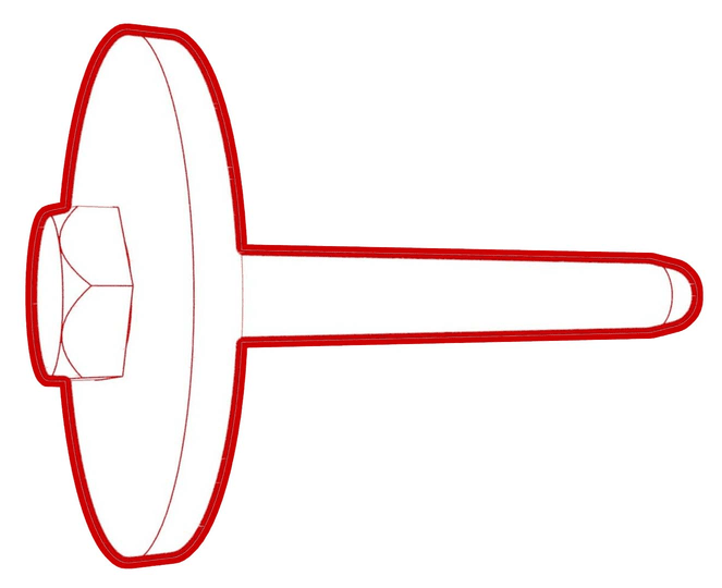 10 Nm (7.4 lbs-ft)
 -
Fasten the clip that attaches the compressor HV electrical harness to the intermediate bracket.
-
Install the compressor under the shock tower brace, and then install the bolts that attach the compressor to the shock tower brace.
 10 Nm (7.4 lbs-ft)
 - Move the compressor HV electrical harness behind the shock tower brace.
-
Fasten the clip that attaches the compressor HV electrical harness to the body.
-
Install a new o-ring onto the suction/liquid line, insert the line into the compressor, and then install the nut that attaches the line to the compressor.
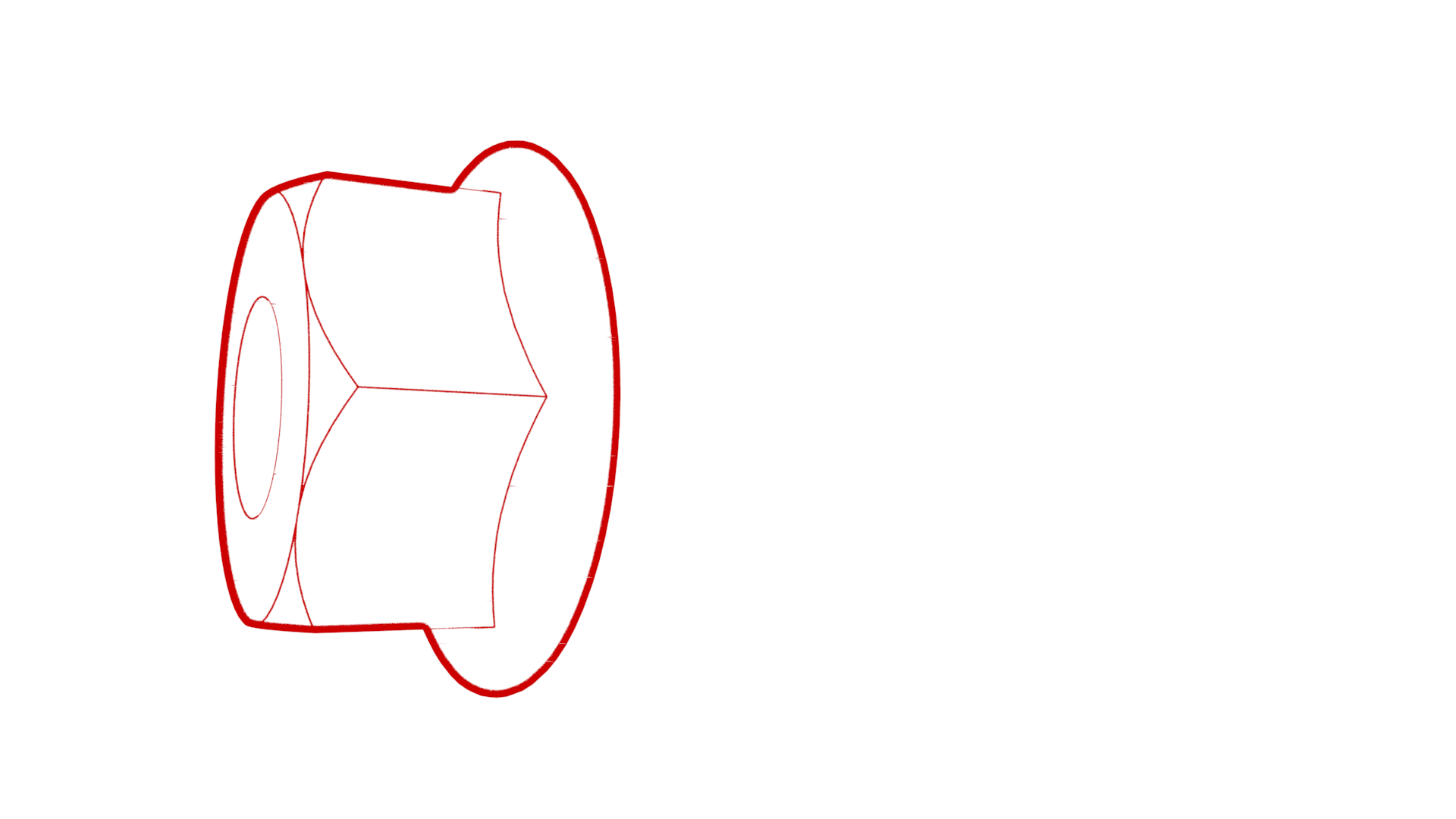 22 Nm (16.2 lbs-ft)
 -
Install a new o-ring onto the discharge line, insert the line into the compressor, and then install the nut that attaches the line to the compressor. .
 22 Nm (16.2 lbs-ft)
 -
Fasten the clip that attaches the suction/liquid lines to the superbottle.
-
Connect the electrical harness to the powertrain coolant pump connector.
-
Fasten the clip that attaches the electrical harness to the suction liquid line.
-
Install new o-rings onto the
suction/liquid line fitting, install the fitting into the chiller and EXV assembly, and
then install the bolt that attaches the fitting to the chiller and EXV assembly.
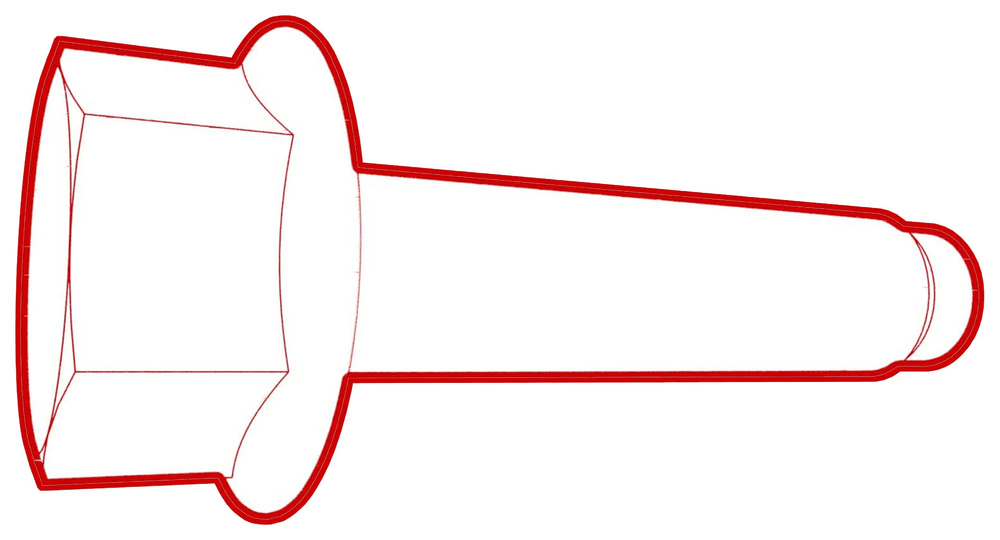 22 Nm (16.2 lbs-ft)
 -
Connect the electrical harness to the low pressure transducer connector.
-
Install the suction/liquid line bracket onto the shock tower brace, and then install the bolt that attaches the bracket to the brace.
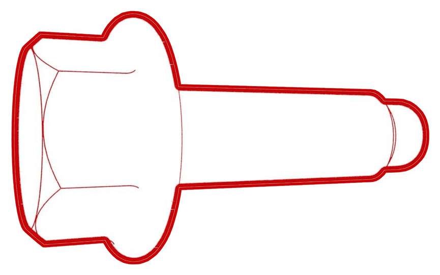 5.5 Nm (4.1 lbs-ft)
 -
Fasten the clips that attach the low voltage electrical harness to the compressor and compressor bracket.
-
Install the bolt that attaches the ground harness to the compressor.
 6 Nm (4.4 lbs-ft)
 -
Connect the low voltage electrical harness to the compressor connector.
- Raise the vehicle.
-
Connect the electrical harness to the high pressure transducer connector.
-
Fasten the clips that attach the compressor HV electrical harness to the bulkhead.
-
Connect the compressor HV electrical connector to the HV electrical harness.
- Install the front aero shield. See Panel - Aero Shield - Front (Remove and Replace).
- Connect the red high pressure hose to the vehicle's high pressure port, and the blue low pressure hose to the vehicle's low pressure port.
- Start the A/C vacuum and leak test, and continue with this procedure while the tests are running.
- Install the ancillary bay HV cap. See Cap - HV - Ancillary Bay (Remove and Replace).
-
Connect 12V power. See 12V/LV Power (Disconnect and Connect).
NoteDo not install the rear apron at this time.
- When the A/C vacuum and leak test is complete, recharge the refrigerant. See A/C Refrigerant (Recovery and Recharge).
- Connect a laptop with Toolbox 3 to the vehicle.
- Update the vehicle firmware. See Software Update.
- After the A/C refrigerant recharge has fully completed, verify the operation of the A/C system.
-
Connect a charge cable to the vehicle, and then use Toolbox to run the TEST-SELF_VCFRONT_X_THERMAL-PERFORMANCEvia Toolbox: (link)via Service Mode: Thermal ➜ Actions ➜ Test Thermal Performancevia Service Mode Plus:
- Drive Inverter ➜ Front Drive Inverter Replacement ➜ Thermal System Test
- Drive Inverter ➜ Rear Drive Inverter Replacement ➜ Thermal System Test
- Drive Inverter ➜ Rear Left Drive Inverter Replacement ➜ Thermal System Test
- Drive Inverter ➜ Rear Right Drive Inverter Replacement ➜ Thermal System Test
- Drive Unit ➜ Front Drive Unit Replacement ➜ Thermal System Test
- Drive Unit ➜ Rear Drive Unit Replacement ➜ Thermal System Test
- Disconnect the charge cable and laptop from the vehicle.
- Install the outer HVAC plenum duct. See Plenum - Inlet - HVAC (Remove and Replace).
- Install the underhood storage unit. See Underhood Storage Unit (Remove and Replace).