Module - Body Controller - Front (Dual Motor) (Non-Heat Pump) (Remove and Replace)
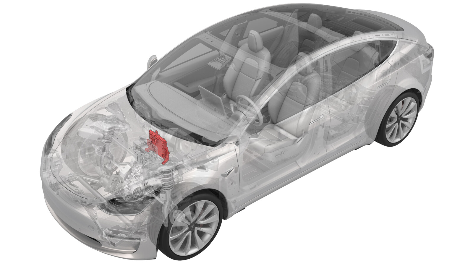 Correction code
17152912
1.32
NOTE: Unless otherwise explicitly
stated in the procedure, the above correction code and FRT reflect all of the work
required to perform this procedure, including the linked procedures. Do not stack correction codes unless
explicitly told to do so.
NOTE: See Flat Rate
Times to learn more about FRTs and how they are created. To provide feedback on
FRT values, email ServiceManualFeedback@tesla.com.
NOTE: See Personal Protection to make sure wearing proper PPE when
performing the below procedure. See Ergonomic Precautions for safe and healthy working practices.
- 2025-04-28: Corrected torque figures for the bolts that attach the shock tower brace to the vehicle.
- 2025-03-10: Updated post-replacement routine.
- 2024-03-18: Added instructions to check the integrity of the controller module cover seal and to replace the cover if any damage is found.
Remove
- Remove the 2nd row lower seat cushion. See Seat Cushion - Lower - 2nd Row (Remove and Replace).
- Remove the rear underhood apron. See Underhood Apron - Rear (Remove and Replace).
- Remove the cabin intake duct. See Duct - Upper - Cabin Intake (Remove and Replace).
- Remove the underhood storage unit. See Underhood Storage Unit (Remove and Replace).
- Remove the LH and RH wiper arms. See Wiper Arms (Remove and Replace).
- Remove the LH and RH shock tower covers. See Cover - Shock Tower - LH (Remove and Replace).
- Remove the cowl screen panel. See Panel - Cowl Screen (Remove and Replace).
- Disconnect 12V power. See 12V/LV Power (Disconnect and Connect).
- Remove the 12V auxiliary battery. See 12V/LV Battery (Remove and Replace).
-
Remove the bolt that attaches the 12V battery rear hook tie down to the body, and then remove the tie down from the body.
-
Remove the nuts (x2) that attach the superbottle to the thermal beam.
-
Remove the upper bolts (x2) that attach the battery bracket to the vehicle.
-
Release the clip that attaches the coolant hose to the 12V battery bracket.
-
Release the clip that attaches the 12V battery vent hose to the 12V battery bracket.
-
Loosen the inner bolts that attach the shock tower brace to the RH shock tower.
-
Loosen the outer bolt that attaches the shock tower brace to the RH shock tower.
-
Remove the inner bolts that attach the shock tower brace to the LH shock tower.
-
Remove the outer bolt that attaches the shock tower brace to the LH shock tower.
- Shift the LH side of the shock tower brace towards the front of the vehicle to increase working space.
-
Remove the bolt that attaches the thermal harness cover to the front body controller module, and then remove the cover from the module.
-
Disconnect the thermal harness from the front body controller module connector.
-
Release the clip that attaches the suction/liquid lines to the body near the TXV, and then move the electrical harness aside to gain access to the front body controller module.
-
Remove the bolts (x9) that attach the front body controller module cover to the front body controller module, and then remove the cover.
NoteCheck the condition of the cover seal; if any damage is found, order a new front body controller module cover.
-
Disconnect the electrical harness from the front body controller module connectors (x4).
-
Remove the nuts (x6) and
bolt that attach the power and ground cables to the front body controller
module.
NoteReuse the bolt and discard the nylon nuts (x6).
-
Remove the bolts (x3) that attach the front body controller module to the body.
-
Release the clips (x2) that attach the bottom of the front body controller module to the body, and then remove the lower busbar from the stud.
-
Remove the bolt that attaches the ground strap to the upper rear of the front body controller module, and then remove the ground strap from the module.
-
Remove the bolt that attaches the ground strap to the lower right side of the front body controller module, and then remove the ground strap from the module.
-
Remove the bolt that attaches the ground strap to the lower rear of the front body controller module, and then remove the ground strap from the module.
-
Remove the front body controller module from the vehicle.
Install
- Set the front body controller module where it installs into the vehicle, and then tilt the module forward
-
Install the ground strap to the lower rear of the front body controller module, and then install the bolt that attaches the ground strap to the module.
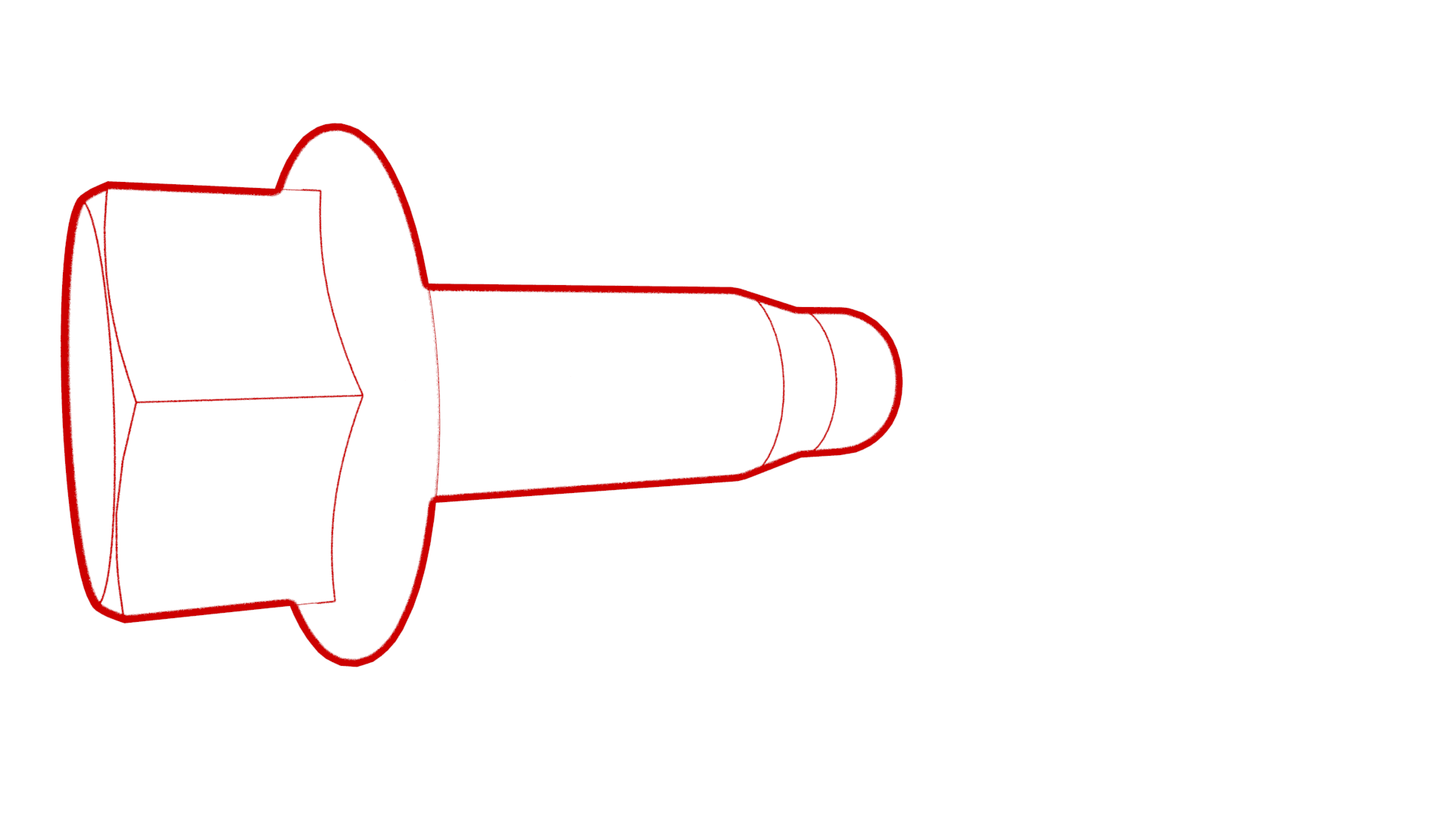 9 Nm (6.6 lbs-ft)
 -
Install the ground strap to the lower right side of the front body controller module, and then install the bolt that attaches the ground strap to the module.
 9 Nm (6.6 lbs-ft)
 -
Install the ground strap to the upper rear of the front body controller module, and then install the bolt that attaches the ground strap to the module.
 9 Nm (6.6 lbs-ft)
 -
Slide the busbar onto the lower stud, and then fasten the electrical harness clips (x2) to the bottom of the front body controller module.
-
Install the bolts (x3) that attach the front body controller module to the body.
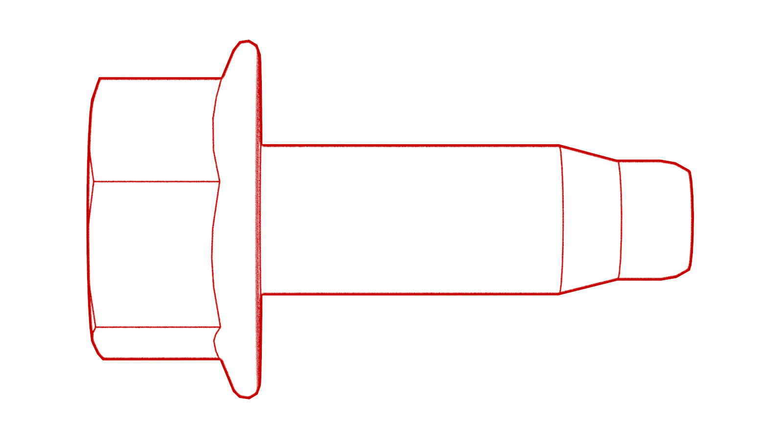 10 Nm (7.4 lbs-ft)
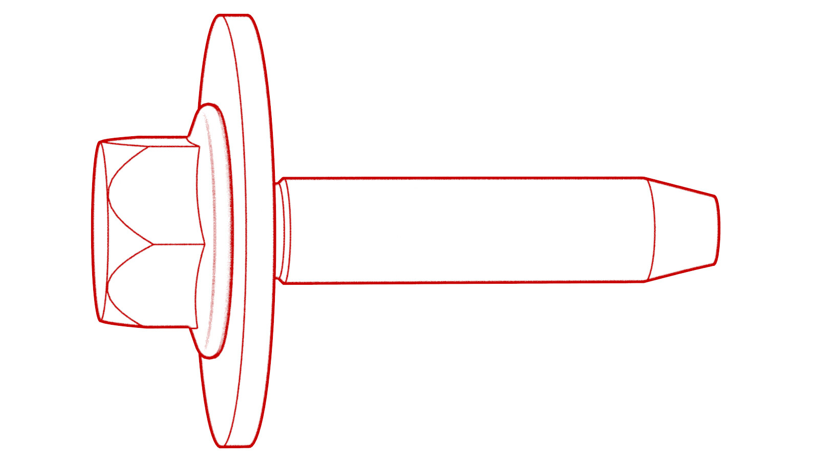 10 Nm (7.4 lbs-ft)
 -
Install new nuts (x6) and
bolt to attach the power and ground cables to the front body controller
module.
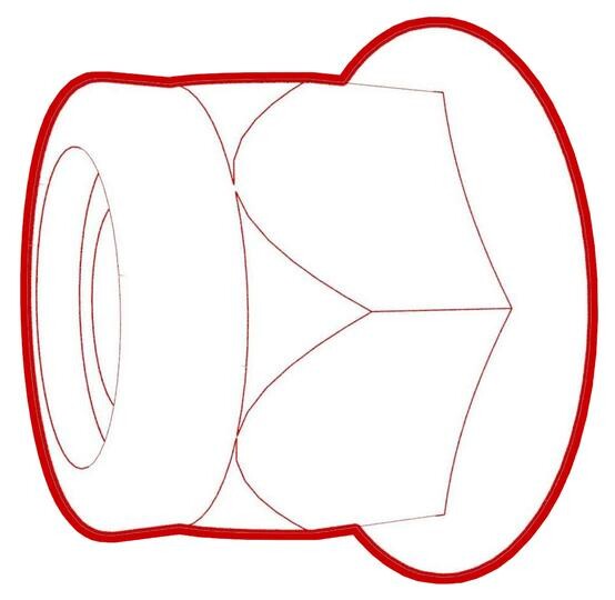 8.5 Nm (6.3 lbs-ft)
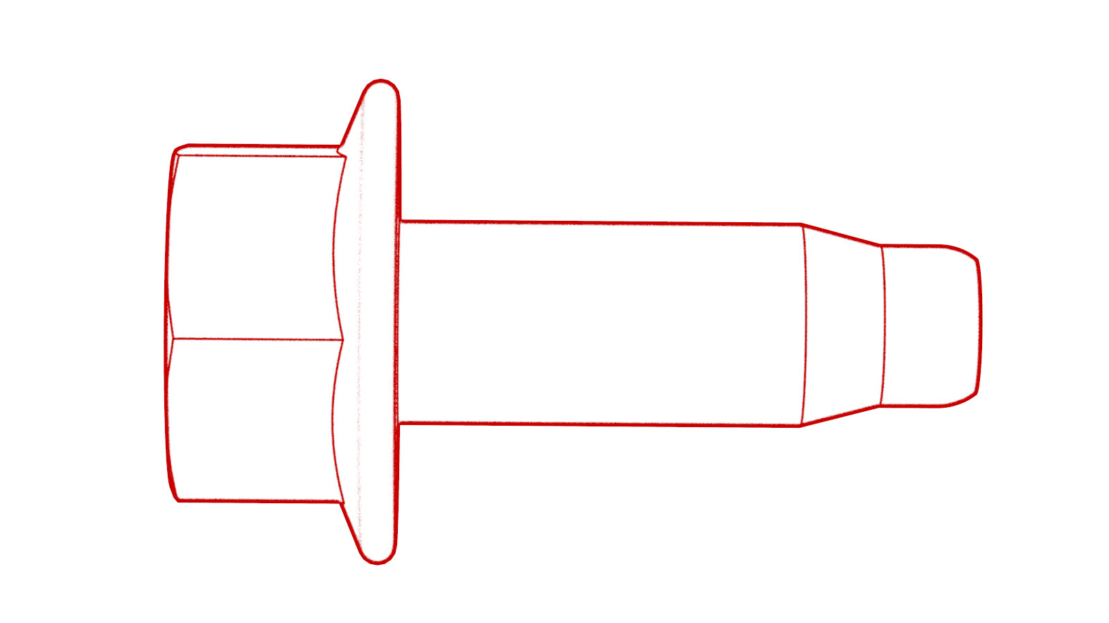 8.5 Nm (6.3 lbs-ft)NoteMake sure that the terminal lugs fit in their channels neatly.
 -
Connect the electrical harness to the front body controller module connectors (x4).
-
Visually inspect that the power and the ground cables exit the front body controller module neatly in their respective channels, and parallel to each other.
CAUTIONMake sure that no cables or wires will be pinched when the front body controller module cover is installed.
-
Install the front body controller module cover to the front body controller module, and then install the bolts (x9) that attach the cover to the module.
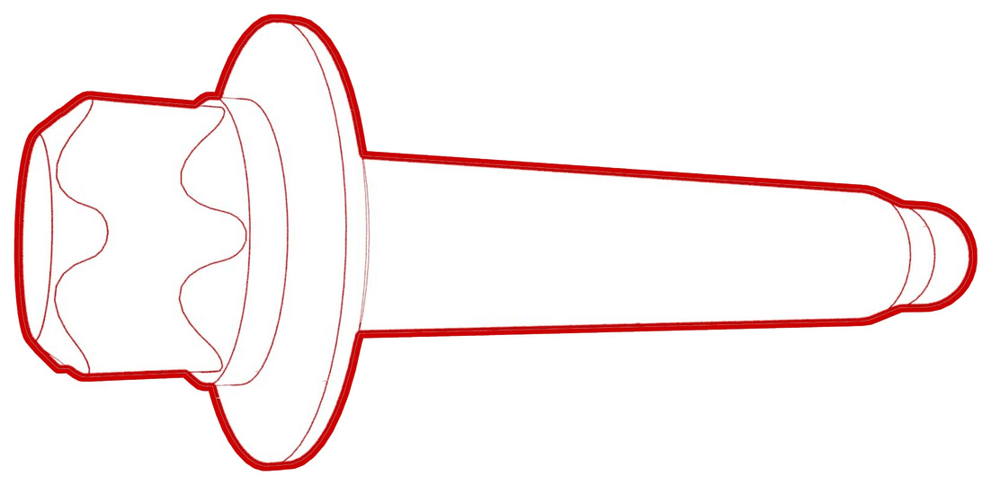 6 Nm (4.4 lbs-ft)CAUTIONMake sure that the cover seal has no damage. If any damage is found, a new front body controller module cover must be installed. Failure to do so may result in water ingress into the front body controller module.
 -
Connect the thermal harness to the front body controller module connector.
-
Fasten the clip that attaches the suction/liquid lines to the body near the TXV.
-
Install the thermal harness cover to the front body controller module, and then install the bolt that attaches the cover to the module.
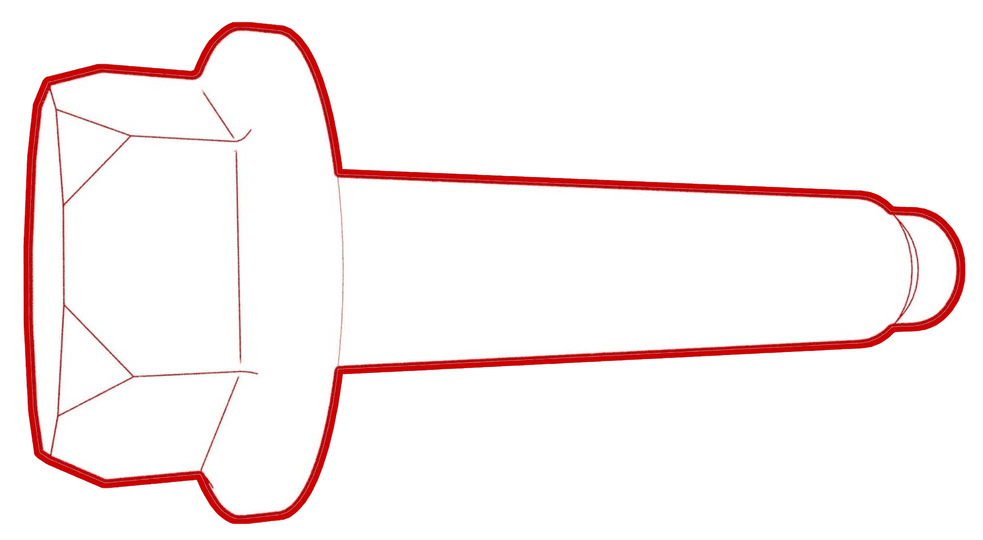 6 Nm (4.4 lbs-ft)
 - Shift the LH side of the shock tower brace rearward so that the bolt holes in the brace and shock tower align.
-
Install the outer bolt that
attaches the shock tower brace to the LH shock tower.
 62 Nm (45.7 lbs-ft)
 -
Install the inner bolts (x2)
that attach the shock tower brace to the LH shock tower.
 55 Nm (40.6 lbs-ft)
 -
Tighten the outer bolt that
attaches the shock tower brace to the RH shock tower.
 62 Nm (45.7 lbs-ft)
 -
Tighten the inner bolts (x2)
that attach the shock tower brace to the RH shock tower.
 55 Nm (40.6 lbs-ft)
 -
Fasten the clip that attaches the 12V battery vent hose to the 12V battery bracket.
-
Fasten the clip that attaches the coolant hose to the 12V battery bracket.
-
Install the upper bolts (x2) that attach the battery bracket to the vehicle.
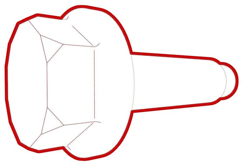 15 Nm (11.1 lbs-ft)
 -
Install the nuts (x2) that attach the superbottle to the thermal beam.
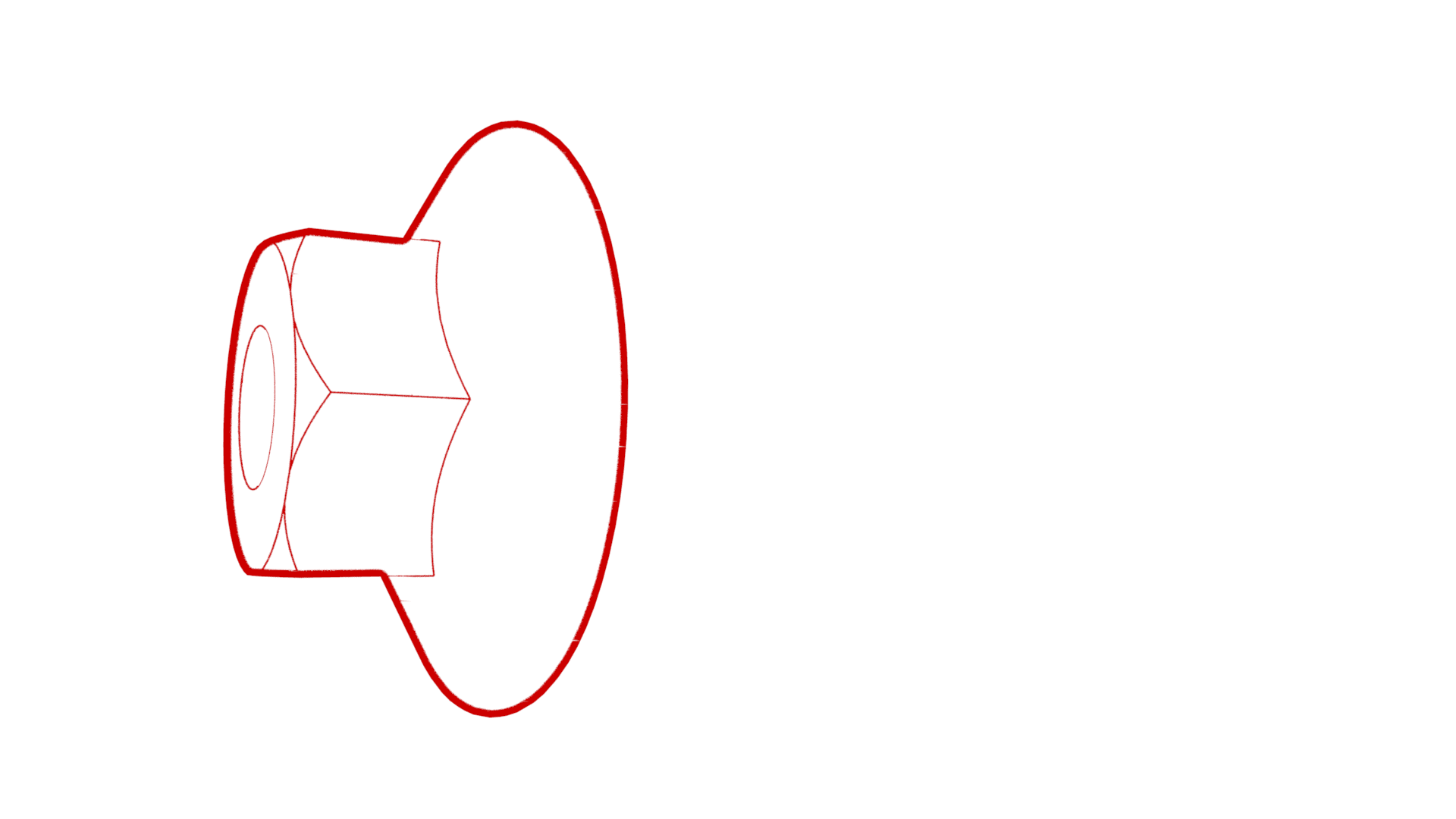 8 Nm (5.9 lbs-ft)
 -
Install the 12V battery rear hook tie down to the body, and then install the bolt that attaches the tie down to the body.
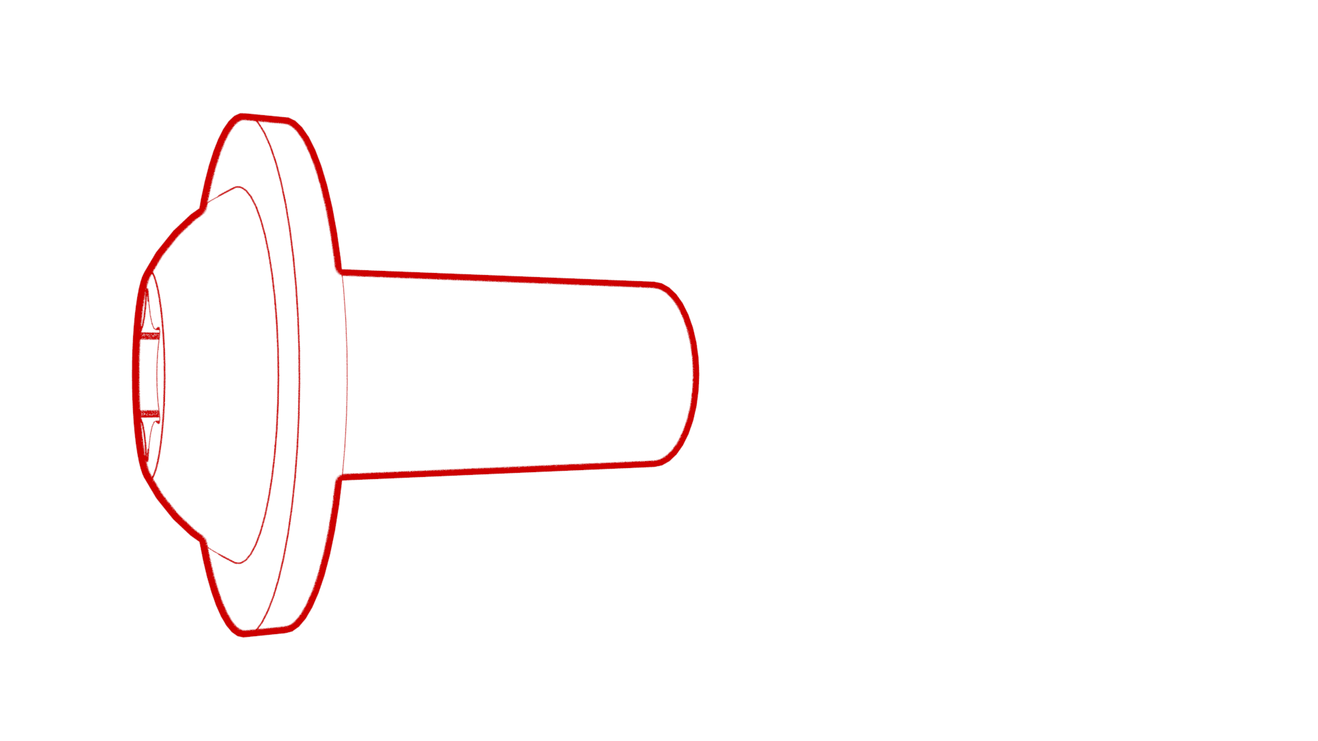 9 Nm (6.6 lbs-ft)
 - Install the 12V auxiliary battery. See 12V/LV Battery (Remove and Replace).
- Connect 12V power. See 12V/LV Power (Disconnect and Connect).
- Reinstall the vehicle firmware. See Software Reinstall - Touchscreen.
- Perform the following routine using Service Mode or Toolbox (see 0005 - Service Modes): PROC_VCFRONT_X_POST-REPLACEMENT-PROCEDUREvia Toolbox: (link)via Service Mode Plus: LowVoltage ➜ VCFRONT Post Replacement ➜ VCFRONT Post Replacement Procedure
- Install the cowl screen panel. See Panel - Cowl Screen (Remove and Replace).
- Install the LH and RH shock tower covers. See Cover - Shock Tower - LH (Remove and Replace).
- Install the LH and RH wiper arms. See Wiper Arms (Remove and Replace).
- Install the underhood storage unit. See Underhood Storage Unit (Remove and Replace).
- Install the cabin intake duct. See Duct - Upper - Cabin Intake (Remove and Replace).
- Install the rear underhood apron. See Underhood Apron - Rear (Remove and Replace).
- Install the 2nd row lower seat cushion. See Seat Cushion - Lower - 2nd Row (Remove and Replace).
- Perform the headlights adjust procedure. See: