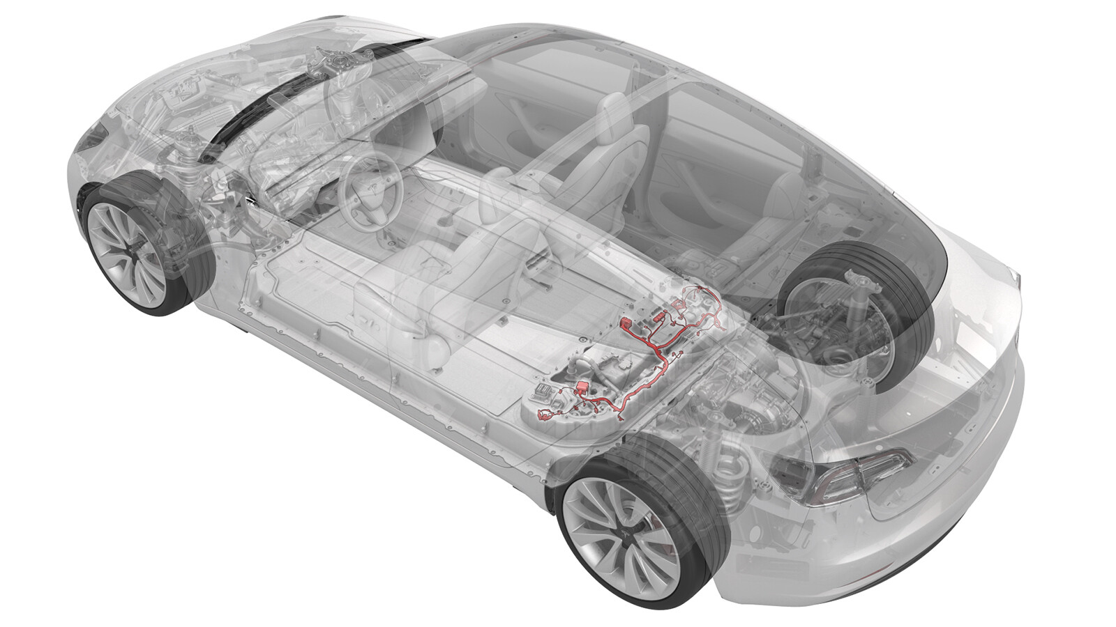
Harness - Ancillary Bay - HV Battery (Remove and Replace)
 Correction code
16305002
3.96
NOTE: Unless otherwise explicitly
stated in the procedure, the above correction code and FRT reflect all of the work
required to perform this procedure, including the linked procedures. Do not stack correction codes unless
explicitly told to do so.
NOTE: See Flat Rate
Times to learn more about FRTs and how they are created.
NOTE: See Personal Protection to make sure wearing proper PPE when
performing the below procedure. NOTE: See Ergonomic Precautions for safe and healthy working
practices.
Correction code
16305002
3.96
NOTE: Unless otherwise explicitly
stated in the procedure, the above correction code and FRT reflect all of the work
required to perform this procedure, including the linked procedures. Do not stack correction codes unless
explicitly told to do so.
NOTE: See Flat Rate
Times to learn more about FRTs and how they are created.
NOTE: See Personal Protection to make sure wearing proper PPE when
performing the below procedure. NOTE: See Ergonomic Precautions for safe and healthy working
practices.
- 2025-11-04: Clarified language in note for new harnesses.
- 2024-08-21: Added note for newer harness version.
- 2023-07-21: Added a video in step 20 of Remove part.
Equipment:
- 1057602-00-A Ratchet, 1/4" Sq Dr, HV Insulated
- 1057603-00-A Ext Bar, Wobble, 1/4" Dr, HV Insulated
- 1057606-00-A Skt, 1/4" Sq Dr, 13mm, HV Insulated
- 1057607-00-A Magnet, Flexible, HV Insulated, 18"
- 1111868-00-B Connector Removal, Coolant, PCS, M3
- 1135762-00-A Kit, Svc Plug, Cooling Hose, Model 3
- 1059330-00-B Skt, 1/4in Dr, 5-Lobe Torx Plus External
- 1475996-00-A UFO Connector Removal Tool
- 1076927-00-A Resistance meter, microohm, Hioki RM 3548
Only
technicians who have completed all required certification courses are permitted to
perform this procedure. Tesla recommends third party service provider technicians
undergo equivalent training before performing this procedure. For more information on
Tesla Technician requirements, or descriptions of the subject matter for third parties,
see HV Certification Requirements. Proper personal protective equipment (PPE) and insulating HV
gloves with a minimum rating of class 0 (1000V) must
be worn at all times a high voltage cable, busbar, or fitting is handled. Refer to Tech Note TN-15-92-003, High Voltage Awareness
Care Points
for additional safety
information.
Remove
- Perform the vehicle electrical isolation procedure. See Vehicle HV Disablement Procedure.
- Drain the coolant from the power conversion system. See Ancillary Bay Coolant (Drain and Refill).
-
Remove the penthouse cover. See
Cover - Ancillary Bay (Remove and Install).
WarningHV insulating gloves and leather glove protectors must be worn throughout the remainder of this procedure. Do not remove gloves or protectors until otherwise noted.
- Remove the pyrotechnic battery disconnect. See Pyrotechnic Battery Disconnect (Remove and Replace).
- Remove the high voltage controller. See Controller - High Voltage (Remove and Replace).
-
Release the clips (x5) that attach the HV battery ancillary bay harness to the hinge tray.
NotePull and unhook to release the flat rectangular clips.
-
Raise the hinge tray vertically, pull up on the tray at each hinge, and then remove the tray from the vehicle.
- Remove the power conversion system. See Power Conversion System (Remove and Replace).
- Remove the HV battery negative contactor. See Contactor - Negative - HV Battery (Remove and Replace).
- Remove the HV battery DC input assembly. See DC Input Assembly - HV Battery (Harness Type) (Remove and Replace).
-
Remove the HV battery fast charge contactor from the ancillary bay. See Contactor - Fast Charge - HV Battery (Remove and Replace).
NoteDo not disassemble the HV battery fast charge contactor assembly after removal.
-
Remove the clip that confines the LH
Hall effect sensor to the LH flood port cover above the LH flood port.
NoteA newer version of the ancillary bay harness is not equipped with a Hall effect sensor. Skip this step and the next step if the harness does not have a Hall effect sensor.
-
Release the tab that holds the LH Hall
effect sensor to the LH flood port cover, and then separate the sensor from under the
tab.
- Remove the 12V DC passthrough. See Passthrough - DCDC - 12V (Busbar Type) (Remove and Replace).
- Remove the HV battery positive contactor. See Contactor - Positive - HV Battery (Remove and Replace).
-
Remove the insulator cap from the nut that joins the positive DC link to the positive busbar.
-
Remove and discard the nut that joins the positive DC link to the positive busbar.
-
Remove the nuts (x2) that attach the positive DC link to the ancillary bay floor, lift the link off of the studs and posts, and then move the link inboard to access the HV battery ancillary bay harness clips.
-
Release the clips that attach the HV battery ancillary bay harness to the positive DC link insulator, and remove the DC link from the ancillary bay.
NoteThe rear most clip is behind the positive DC link insulator.
-
Use the UFO connector removal tool to disconnect the RH passthrough connector from the HV battery module 4 BMS connector.
CAUTIONDo not try to remove the RH passthrough in this step, as it will be damaged. Only disconnect the connector.TIpAccess the ancillary bay from the RH rear door area for this step.WarningThe video(s) included in this procedure are meant as an overview for supplemental purposes only. Follow all of the steps listed in the procedure to avoid damage to components and/or personal injury.
Figure 1. View From RH Rear Door -
Use a pry tool to release the RH passthrough clips (x3) that attach the RH passthrough to the posts of the ancillary bay floor, and then separate the passthrough from the ancillary bay floor.
-
Remove the clip that confines the RH
Hall effect sensor to the RH flood port cover above the RH flood port.
-
Release the tab that holds the RH Hall
effect sensor to the RH flood port cover, and then separate the sensor from under the
tab.
-
Remove the cable ties that attach the
HV battery ancillary bay harness to the power conversion system DC bus HV harness on
either side of the RH Hall effect sensor.
-
Release the clips that attach the fuse access insulator to the RH ancillary bay bus cover, and remove the insulator.
- If installed, release the clips that attach the shunt access insulator over the shunt, and remove the insulator.
-
Release the clips (x4) that attach the HV battery ancillary bay harness along the busbar insulator.
-
Release the HV battery ancillary bay harness from under the respective tabs, and disconnect the harness from the A/C compressor and PTC heater high voltage interlock loop connector , the rear drive unit high voltage interlock loop connector, and the shunt connector.
-
Release the clips that attach the pyrotechnic battery disconnect connector to the ancillary bay floor, and separate the connector from the floor.
-
If the vehicle is configured with dual motors, release the HV battery ancillary bay harness from under the tab, and disconnect the harness from the front drive unit high voltage interlock loop connector.
-
Release the clip that attaches the HV battery ancillary bay harness to the post near the LH UFO.
NotePull and unhook to release the flat rectangular clip.
-
Use the UFO connector removal tool to disconnect the LH passthrough connector from the HV battery module 1 BMS connector.
CAUTIONDo not try to remove the LH passthrough in this step, as it will be damaged. Only disconnect the connector.TIpAccess the ancillary bay from the LH rear door area for this step.
-
Use a pry tool to release the LH passthrough clips (x3) that attach the LH passthrough to the posts of the ancillary bay floor, remove the passthrough, and then remove the HV battery ancillary bay harness from the vehicle.
Install
- Perform a zero adjust of the Hioki resistance meter in preparation to measure resistances later in this procedure. See Resistance Meter (Zero Adjust).
-
Lay the HV battery ancillary bay harness down inside of the ancillary bay.
NoteThe large fast charge contactor connector goes on the LH side near the LH passthrough to the HV battery.
- Install the LH passthrough onto the posts at the LH ancillary bay floor, and then press the passthrough down to fasten the passthrough clips (x3).
- Press the center of the LH passthrough to connect the passthrough connector to the HV battery module 1 BMS connector.
-
Fasten the clip that attaches the HV battery ancillary bay harness to the post near the LH UFO.
-
If the vehicle is configured with dual motors, connect the HV battery ancillary bay harness to the front drive unit high voltage interlock loop connector, and then fasten the harness under the tab.
-
Install the pyrotechnic battery disconnect connector into the ancillary bay floor, and then fasten the clips that attach the connector to the floor.
-
Connect the HV battery ancillary bay harness to the shunt connector, the rear drive unit high voltage interlock loop connector, the A/C compressor and PTC heater high voltage interlock loop connector, and then fasten the harness under the respective tabs.
-
Fasten the clips (x4) that attach the HV battery ancillary bay harness along the busbar insulator.
- If removed, install the shunt access insulator over the shunt, and then fasten the clips that attach the insulator to the shunt.
-
Install the fuse access insulator to the RH ancillary bay bus cover, and then fasten the clips that attach the insulator to the cover.
-
Fasten the RH Hall effect sensor under
the tab of the RH flood port cover.
NoteA newer version of the ancillary bay harness is not equipped with a Hall effect sensor. Skip this step and the next step if the harness does not have a Hall effect sensor.
-
Install the clip that confines the RH
Hall effect sensor to the RH flood port cover above the RH flood port.
-
Install new cable ties on either side
of the RH Hall effect sensor to attach the HV battery ancillary bay harness to the power
conversion system DC bus HV harness.
- Install the RH passthrough onto the posts at the RH ancillary bay floor, and then press the passthrough down to fasten the passthrough clips (x3).
- Press the center of the RH passthrough to connect the passthrough connector to the HV battery module 4 BMS connector.
-
Bring the positive DC link to the ancillary bay, and then fasten the clips that attach the HV battery ancillary bay harness to the positive DC link insulator.
- Use an IPA wipe to clean the HV mating surfaces of the positive DC link and the positive busbar.
-
Install the positive DC link onto the studs and posts of the ancillary bay floor, and then install the nuts (x2) that attach the link to the floor.
 6 Nm (4.4 lbs-ft)
 -
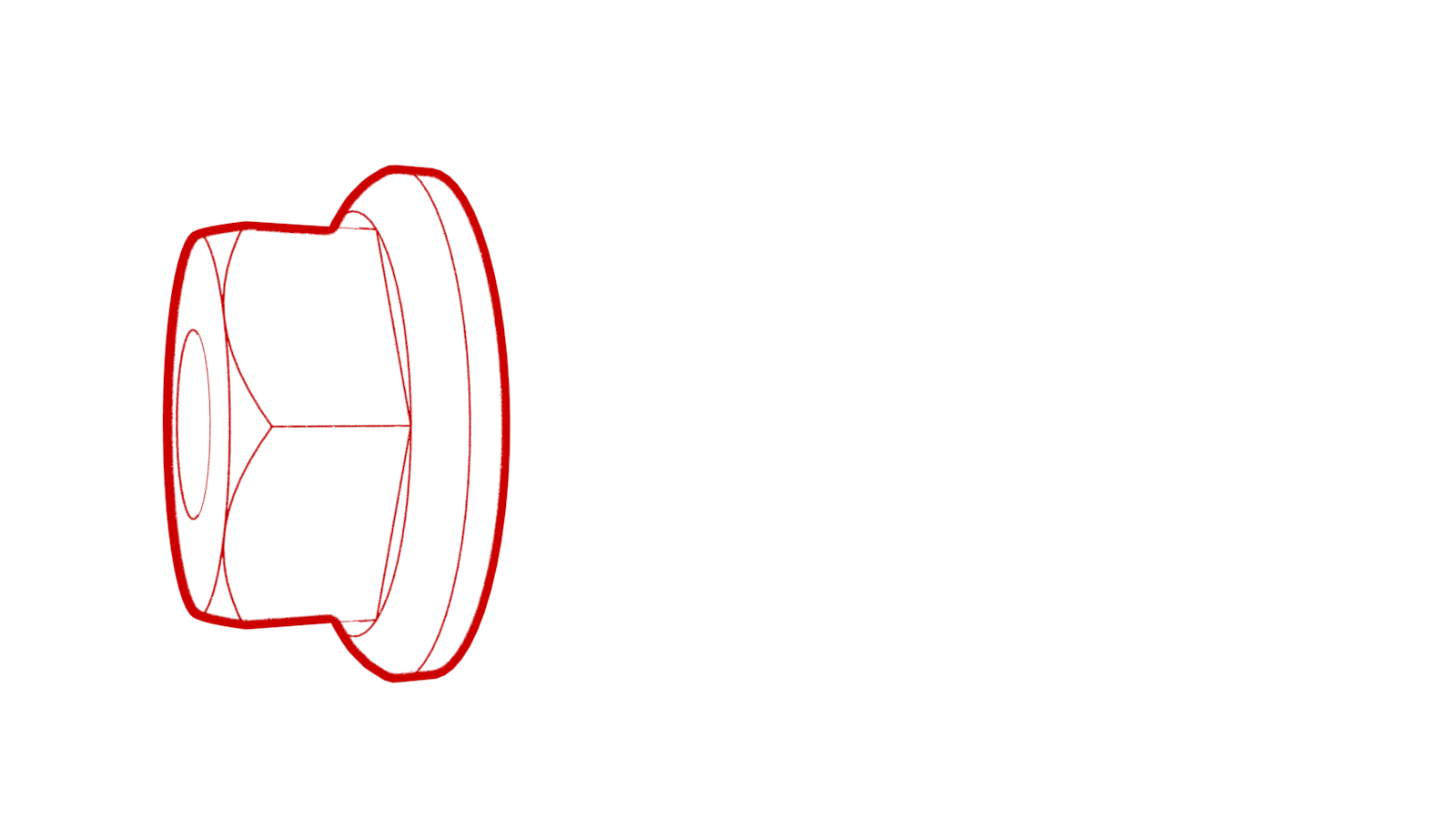
Install a new nut to join the positive DC link to the positive busbar.
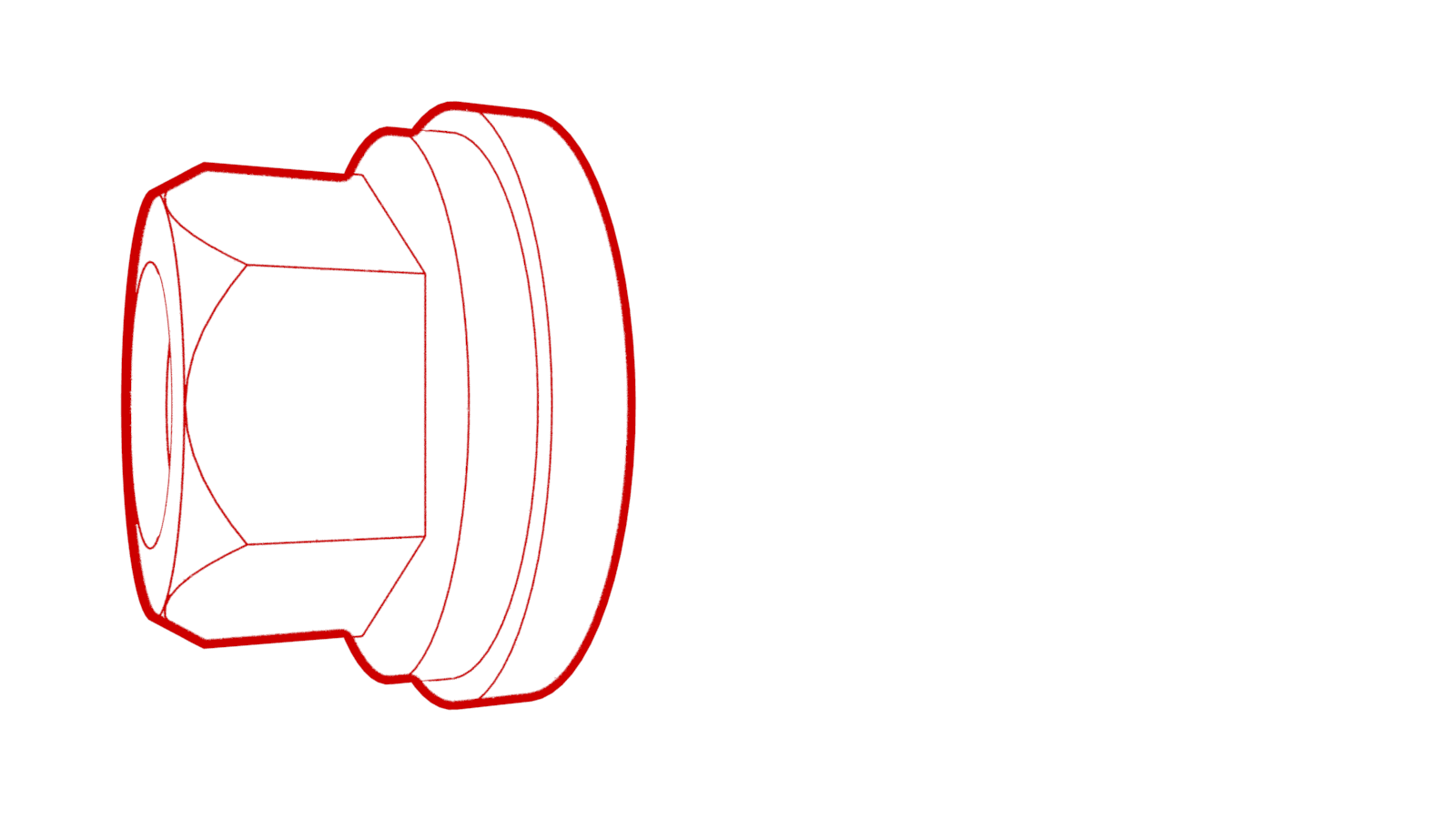 9 Nm (6.6 lbs-ft)
 -
Use the Hioki resistance meter to measure the resistance at the joint between the positive DC link and the positive busbar.
NoteThe maximum acceptable resistance is 0.060 mΩ (60 μΩ). There is too much resistance in the High Voltage joint. Remove the fastener, clean areas with isopropyl alcohol, install fastener back and test again
Figure 2. Generic Measurement - Actual busbars and fasteners might appear different -
Install the insulator cap onto the nut that joins the positive DC link to the positive busbar.
- Install the HV battery positive contactor. See Contactor - Positive - HV Battery (Remove and Replace).
- Install the 12V DC passthrough. See Passthrough - DCDC - 12V (Busbar Type) (Remove and Replace).
-
Fasten the LH Hall effect sensor under
the tab of the LH flood port cover.
-
Install the clip that confines the LH
Hall effect sensor to the LH flood port cover above the LH flood port.
- Install the HV battery fast charge contactor into the ancillary bay. See Contactor - Fast Charge - HV Battery (Remove and Replace).
- Install the HV battery DC input assembly. See DC Input Assembly - HV Battery (Harness Type) (Remove and Replace).
- Install the HV battery negative contactor. See Contactor - Negative - HV Battery (Remove and Replace).
- Install the power conversion system, perform an ancillary bay coolant leak test, and refill the coolant. See Power Conversion System (Remove and Replace).
-
Install the hinge tray vertically onto the hinges, press down on the tray at each hinge so that the tray attaches to the hinges, and then lower the tray.
-
Fasten the clips (x5) that attach the HV battery ancillary bay harness to the hinge tray.
- Install the high voltage controller. See Controller - High Voltage (Remove and Replace).
- Measure the voltage across the pyrotechnic battery disconnect mount points, and then install the pyrotechnic battery disconnect. See Pyrotechnic Battery Disconnect (Remove and Replace).
- Install the ancillary bay cover and connect 12V power. See Cover - Ancillary Bay (Remove and Install).