HV Harness - Charge Port Busbar (NACS) (Remove and Replace)
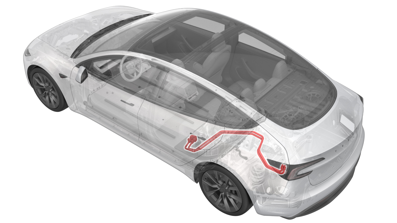 Correction code
4450010302
FRT
0.84
NOTE: Unless
otherwise explicitly stated in the procedure, the correction code and its
associated FRT reflect all of the work required to perform this procedure,
including the linked procedures. Do not stack correction
codes unless explicitly told to do so.
NOTE: See Flat Rate Times to
learn more about FRTs and how they are created.
NOTE: See Personal Protection to make
sure you are wearing proper PPE when performing the procedure below.
NOTE: See Ergonomic Precautions for safe and healthy
working practices.
Correction code
4450010302
FRT
0.84
NOTE: Unless
otherwise explicitly stated in the procedure, the correction code and its
associated FRT reflect all of the work required to perform this procedure,
including the linked procedures. Do not stack correction
codes unless explicitly told to do so.
NOTE: See Flat Rate Times to
learn more about FRTs and how they are created.
NOTE: See Personal Protection to make
sure you are wearing proper PPE when performing the procedure below.
NOTE: See Ergonomic Precautions for safe and healthy
working practices.
- 2026-08-21: Released new procedure.
Equipment:
- 1076921-00-A FLUKE DIGITAL MULTIMETER 1587
- 1130480-02-A Slim Test Probes
- 1076927-00-A Hioki RM 3548
- 1076928-00-A Test Probes - Hioki 9461
Only
technicians who have completed all required certification courses are permitted to
perform this procedure. Tesla recommends third party service provider technicians
undergo equivalent training before performing this procedure. For more information on
Tesla Technician requirements, or descriptions of the subject matter for third parties,
see HV Certification Requirements. Proper personal protective equipment (PPE) and insulating HV
gloves with a minimum rating of class 0 (1000V) must
be worn at all times a high voltage cable, busbar, or fitting is handled. Refer to Tech Note TN-15-92-003, High Voltage Awareness
Care Points
for additional safety
information.
Remove all jewelry (watches, bracelets, rings, necklaces, earrings, ID tags, piercings, etc.) from your person, and all objects (keys, coins, pens, pencils, tools, fasteners, etc.) from your pockets before performing any procedure that exposes you to high voltage.
Proper Personal Protective Equipment (PPE) is required to perform this procedure:
- High Voltage (HV) insulating gloves
- Leather glove protectors
- High voltage glove tester
- Safety glasses
- Electrical hazard rated safety shoes
A glove inflator is the only recommended way to test HV gloves. Both HV gloves must pass testing before beginning this procedure. If either glove does not pass the air check, discard the pair.
Make sure that the HV gloves are not expired. HV gloves can be used up to 12 months after the testing date printed on the glove, but only 6 months after first use even if the gloves are still within the 12-month period.
Torque Specifications
| Description | Torque Value | Recommended Tools | Reuse/Replace | Notes |
|---|---|---|---|---|
| Nuts (x2) that attach the charge port busbar leads to the charge port assembly |
 9 Nm (6.6 lbs-ft) |
|
Reuse | |
| Busbar access door bolt |
9 Nm (6.6 lbs-ft) |
|
Reuse | |
| Bolts (x2) that attach the charge port busbars to the HV header |
9 Nm (6.6 lbs-ft) |
|
Reuse | |
| Busbar studs at the back of the charge port |
2 Nm (1.5 lbs-ft) |
|
N/A |
Remove
- Open the trunk.
- Lower all the windows and open all the doors.
- Move the LH and RH front seats forward.
- Perform the Vehicle HV Disablement Procedure. See Vehicle HV Disablement Procedure (Test/Adjust).
- Remove the LH 2nd row seat cushion bracket. See Bracket - Edge Support - Seat Cushion - 2nd Row - LH (Remove and Replace).
- Remove the LH trunk side trim. See Trim - Side - Trunk - LH (Remove and Replace).
-
Release the white lock tab and then
disconnect the DC logic connector from the charge port assembly.
- Put on HV insulating gloves and leather over gloves.
-
Use a pick to gently release the tabs
(x2) that attach the safety cap to the busbar brackets, and then remove the safety
cap.
NoteDo not pry with excessive force, as doing so could damage the safety cap.
-
Remove the nuts (x2) that attach the
charge port busbar leads to the charge port assembly.
TipUse of the following tool(s) is recommended:
- 10 mm deep socket
- Flex head ratchet/flex head torque wrench
- Ratchet/torque wrench
- Electrical Protective Gloves
-
Remove the bolt that closes the charge
port busbar access door at the ancillary bay HV header, and then open the access
door.
TipUse of the following tool(s) is recommended:
- Insulated
tools:
- Extension 1/4 Dr. Wobble 10.5"
- Ratchet/torque wrench
- 10 mm deep socket
- Electrical Protective Gloves
- Insulated
tools:
-
Remove the bolts (x2) that attach the
charge port busbars to the HV header.
TipUse of the following tool(s) is recommended:
- Insulated
tools:
- Extension 1/4 Dr. Wobble 10.5"
- Ratchet/torque wrench
- 10 mm deep socket
- Electrical Protective Gloves
- Insulated
tools:
-
Lift and remove the charge port busbar
connector from the HV header.
NoteWiggle the connector back and forth to ease removal.WarningThe video(s) included in this procedure are meant as an overview for supplemental purposes only. Follow all of the steps listed in the procedure to avoid damage to components and/or personal injury.
-
With assistance, remove the charge
port busbars out through the trunk.
NoteManeuver the busbars through the body harness, rotating the busbars as needed.
Replace
-
Clean the HV header contact surface
with an IPA wipe, and allow to dry for 1 minute.
-
With assistance, position the charge
port busbars for installation by inserting the busbars through the trunk.
NoteManeuver the busbars through the body harness, rotating the busbars as needed.
-
With assistance, align the guide tabs
on the HV header with the charge port busbar connector, and then install the busbar
connector on the HV header.
TipGently lift the rear half of the busbars to aid installation of the busbars on the HV header.NoteIf positioning the busbars requires excessive force, the busbars might be bent. Inspect for damage and replace the busbars if necessary.
-
Install the bolts (x2) that attach the
charge port busbars to the HV header.9 Nm (6.6 lbs-ft)TipUse of the following tool(s) is recommended:
- Insulated
tools:
- Extension 1/4 Dr. Wobble 10.5"
- Ratchet/torque wrench
- 10 mm deep socket
- Electrical Protective Gloves
- Insulated
tools:
-
Close the charge port busbar access
door, and then install the bolt on the access door.9 Nm (6.6 lbs-ft)TipUse of the following tool(s) is recommended:
- Insulated
tools:
- Extension 1/4 Dr. Wobble 10.5"
- Ratchet/torque wrench
- 10 mm deep socket
- Electrical Protective Gloves
- Insulated
tools:
-
Install the nuts (x2) that attach the charge port busbar leads to the charge port
assembly.9 Nm (6.6 lbs-ft)NoteIf positioning the busbars requires excessive force, the busbars might be bent. Inspect for damage and replace the busbars if necessary.TipUse of the following tool(s) is recommended:
- 10 mm deep socket
- Flex head ratchet/flex head torque wrench
- Ratchet/torque wrench
- Electrical Protective Gloves
-
Install the safety cap on the busbar
brackets, making sure to engage the two locking tabs.
- Remove the HV insulating gloves and leather over gloves.
-
Connect the DC logic connector to the
charge port assembly and then engage the white lock tab.
- Install the LH 2nd row seat cushion bracket. See Bracket - Edge Support - Seat Cushion - 2nd Row - LH (Remove and Replace).
- Install the LH trunk side trim. See Trim - Side - Trunk - LH (Remove and Replace).
- Install the 2nd row lower seat cushion. See Seat Cushion - 2nd Row (Remove and Replace).
- Connect the LV power. See LV Power (Disconnect and Connect) (Modify).
- Move the LH and RH front seats back to their original position.
- Raise all the windows and close all the doors.
- Close the trunk.