2025-10-23
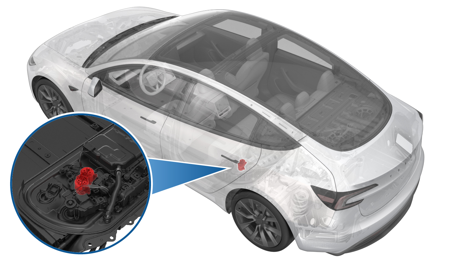
Contactor - Fast Charge - HV Battery (Remove and Replace)
 Correction code
1630010122
FRT
1.56
NOTE: Unless otherwise explicitly stated in the procedure, the correction code and FRT listed above reflect all of the work required to perform this procedure, including the linked procedures. Do not stack correction codes unless explicitly told to do so.
NOTE: See Flat Rate Times to learn more about FRTs and how they are created.
NOTE: See Personal Protection to make sure you
are wearing proper PPE when performing the procedure below.
NOTE: See Ergonomic Precautions for safe and healthy working practices.
Correction code
1630010122
FRT
1.56
NOTE: Unless otherwise explicitly stated in the procedure, the correction code and FRT listed above reflect all of the work required to perform this procedure, including the linked procedures. Do not stack correction codes unless explicitly told to do so.
NOTE: See Flat Rate Times to learn more about FRTs and how they are created.
NOTE: See Personal Protection to make sure you
are wearing proper PPE when performing the procedure below.
NOTE: See Ergonomic Precautions for safe and healthy working practices.
- 2025-10-23: Torque values in Installation step 2 corrected.
Equipment:
- 1076921-00-A Fluke 1587
- 1059330-00-B Skt, 1/4in Dr, 5-Lobe Torx Plus External
- 1057602-00-A Ratchet, 1/4" Sq Dr, HV Insulated
- 1467483-00-C M3/Y Ancillary Bay Service Insulator Kit
- 1131071-00-A Dummy Disconnect, Pyro, Safety
- 1057605-00-A Skt, 1/4" Dr, 10mm, Univ, HV Insu
- 1453448-01-A Kit Digital Multimeter Set EXTECH 335
- 1076928-00-A Test Probes - Hioki 9461
- 1133768-00-C Insulated Socket 1/4in Dr. 12pt. Deep x 10mm
- 1108272-00-B Cap, Logic Conn, Inv, 3DU
- 1057606-00-A Skt, 1/4" Sq Dr, 13mm, HV Insulated
- 1076927-00-A Hioki tester
| Description | Torque Value | Recommended Tools | Reuse/Replace | Notes |
|---|---|---|---|---|
| Patch bolts that attach the DC link negative busbar, the DC link positive busbar, and the positive inlet fast charge busbar to the fast charge contactor |
 15 Nm (11.1 lbs-ft) - 180 degrees 5 Nm (3.7 lbs-ft) + 60 degrees |
|
Replace | |
| Bolts that attach the fast charge contactor to the lower fast charge insulator assembly |
5.5 Nm (4.1 lbs-ft) |
|
Reuse |
Remove
- Remove the negative inlet fast charge busbar. See Busbar - Fast Charge - Input - Negative (Remove and Replace).
-
Remove and discard the patch bolts
(x3) that attach the DC link negative busbar, the DC link positive busbar, and the
positive inlet fast charge busbar to the fast charge contactor.
TIpUse of the following tool(s) is recommended:
- 13 mm socket
- Torque wrench with angle measurement
-
Remove the bolts (x3) that attach the
fast charge contactor to the lower fast charge insulator assembly.
TIpUse of the following tool(s) is recommended:
- Socket External Torx 1/4in Dr. E8
Install
-
Install the bolts (x3) that attach the
fast charge contactor to the lower fast charge insulator assembly.5.5 Nm (4.1 lbs-ft)NoteMark after torque.TIpUse of the following tool(s) is recommended:
- Socket External Torx 1/4in Dr. E8
-
Install and torque the new patch bolts
(x3) that attach the DC link negative busbar, the DC link positive busbar, and the
positive inlet fast charge busbar to the fast charge contactor to the first value, then
loosen the bolts by 180 degrees, and then torque to the final value.15 Nm (11.1 lbs-ft) - 180 degrees5 Nm (3.7 lbs-ft) + 60 degreesTIpUse of the following tool(s) is recommended:
- 13 mm socket
- Torque wrench with angle measurement
- Install the negative inlet fast charge busbar. See Busbar - Fast Charge - Input - Negative (Remove and Replace).