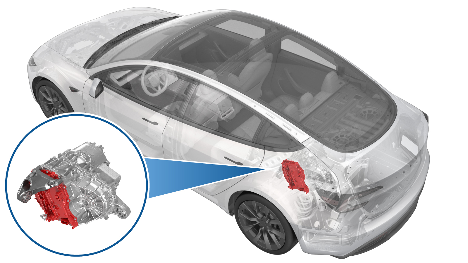
Drive Unit - Rear Drive Inverter (4DU) (Remove and Replace)
 Correction code
4001020132
FRT
3.24
NOTE: Unless
otherwise explicitly stated in the procedure, the above correction code and
FRT reflect all of the work required to perform this procedure, including
the linked procedures. Do
not stack correction codes unless explicitly told to do so.
NOTE: See Flat Rate
Times to learn more about FRTs and how
they are created. To provide feedback on FRT values, email ServiceManualFeedback@tesla.com.
NOTE: See Personal Protection
to make sure wearing proper PPE when performing the below procedure.
NOTE: See Ergonomic Precautions for safe and
healthy working practices.
Correction code
4001020132
FRT
3.24
NOTE: Unless
otherwise explicitly stated in the procedure, the above correction code and
FRT reflect all of the work required to perform this procedure, including
the linked procedures. Do
not stack correction codes unless explicitly told to do so.
NOTE: See Flat Rate
Times to learn more about FRTs and how
they are created. To provide feedback on FRT values, email ServiceManualFeedback@tesla.com.
NOTE: See Personal Protection
to make sure wearing proper PPE when performing the below procedure.
NOTE: See Ergonomic Precautions for safe and
healthy working practices.
- 2024-12-04: Updated inverter fastener torque sequence.
Remove
- Inspect the vehicle for abnormal tire wear that might indicate the need for a wheel alignment. Note any findings.
- Raise and support the vehicle. See Raise Vehicle - 2 Post Lift.
- Open all doors and lower all windows.
-
Connect a laptop with Toolbox to the
vehicle. See Toolbox (Connect and Disconnect).
NoteUpon successful connection, Service Mode Plus will be enabled, and the "Service Mode Plus" watermark will appear on the touchscreen.
-
On the touchscreen, tap the Service
Mode "wrench" (at the bottom of the touchscreen UI), and then tap , tap
Run
, and allow the routine to complete. -
Tap , tap
Run
, and allow the routine to complete. -
Tap , tap
Run
, and allow the routine to complete. - Disconnect the laptop with Toolbox from the vehicle. See Toolbox (Connect and Disconnect).
- Remove the rear underhood apron. See Underhood Apron - Rear (Remove and Replace).
- Disconnect LV power. See LV Power (Disconnect and Connect).
- Remove the fresh air gutter. See Assembly - Fresh Air Gutter - HVAC (Remove and Replace).
- Remove the 2nd row lower seat cushion, See Seat Cushion - 2nd Row (Remove and Replace).
- Perform Vehicle HV Disablement Procedure. See Vehicle HV Disablement Procedure (Test/Adjust).
- Remove the rear wheels. See Wheel Assembly (Remove and Install).
- Remove the rear aero shield panel, See Panel - Aero Shield - Rear (Remove and Replace).
- Remove the LH and RH rear suspension covers. See Cover - Rear Suspension - LH (Remove and Replace).
- Remove the rear fascia assembly. See Fascia Assembly - Rear (Remove and Install).
-
Remove the nut that attaches the rear
drive unit ground strap to the body.
TIpUse of the following tool(s) is recommended:
- 10 mm 12-point deep socket
- Ratchet/torque wrench
-
Disconnect the RH subframe harness
electrical connector.
-
Remove the RH side subframe harness
clips (x2) from body.
-
Remove and discard the nuts (x2) that
attach the stabilizer bar to the end links, and then remove the stabilizer bar from the
end links.
NoteLoosen the nut first, and then continue to remove the nut by counter-holding the ball joint with a hex wrench.NoteMight need to move the rear stabilizer bar up/down to get the correct angle in order to remove the end links.TIpUse of the following tool(s) is recommended:
- 15 mm socket
- Flex head ratchet/flex head torque wrench
-
Release clips (x4) that secure the
coolant hoses to LH and RH shear plates.
Figure 1. LH Shown, RH Similar - Remove the HV battery rear skid plate enclosure. See Skid Plate - HV Battery - Rear (Remove and Replace).
- Remove the rear drive unit inverter inlet hose. See Hose - Inlet - Rear Drive Unit Inverter (Remove and Replace).
-
Release the rear drive unit logic
connection.
NoteDo not get coolant ingress into this connector. Move the connector aside as needed.
-
Release the rear drive unit logic
connection clip.
- Remove the rear drive unit HV harness assembly. See HV Harness - HV Battery to Rear Drive Unit (Remove and Replace).
- Remove the rear drive unit mount. See Mount - Rear Drive Unit - LH (4DU) (Remove and Replace).
-
Rotate the clip counter-clockwise to
release, and then remove the NVH cover from the rear drive unit.
-
Put on ESD wrist strap and secure it
to inverter housing.
-
Remove and discard the label from
phase cover.
-
Remove the bolts (x2) that attach the
rear drive unit phase out cover to the rear drive unit gearbox, and then use a plastic
trim tool to remove the cover from the gearbox.
TIpUse of the following tool(s) is recommended:
- External Torx Plus EP10
-
Inspect the condition of the phase out
cover and O-rings. If the cover has less than 6 O-rings, or if the O-rings or cover are
damaged, discard the cover and use a new cover, part 1096984-00-E or newer revision, for
installation.
NoteUse a plastic trim tool to aid in removal. If the phase out cover or O-rings are damaged then replace with a new one.
-
Remove and discard the bolts (x3) that
attach the rear drive unit motor 3-phase terminals to the rear drive unit LH inverter
3-phase terminals.
TIpUse of the following tool(s) is recommended:
- 10 mm socket
-
Remove and discard the bolts (x9) that
attach the rear drive unit inverter to the gearbox assembly.
TIpUse of the following tool(s) is recommended:
- External Torx Plus EP10
-
Carefully remove the rear drive unit
inverter from the rear drive unit gearbox, and move the inverter down and out between
the rear subframe and drive unit.
NoteTake care not to damage the inverter circuit board when removing the inverter.
-
Remove the plugs from the inverter and
drain the coolant.
-
Set the rear drive unit inverter onto
an ESD mat, and then remove the ESD wrist strap clip from the inverter housing.
NoteDo not place inverter facing downwards on the circuit board as it is fragile.
Install
-
Prepare the new rear drive unit
inverter and attach the ESD strap to the new inverter housing
-
Use an IPA wipe to clean the phase
terminals of the rear drive unit motor and the new rear drive unit inverter, and allow
at least one minute to dry.
-
Carefully install the new rear drive
unit inverter in and up between the rear subframe and rear drive unit. Align the
inverter to the 2 pins in the rear drive unit gearbox, and then install the inverter to
the gearbox.
CAUTIONTake care not to damage the inverter circuit board when installing the inverter.NoteMake sure that the phase terminals align during installation.
-
Install and hand-tighten new bolts
(x9) (1100020-00-A or newer) that attach the new rear drive unit inverter to the rear
drive unit LH gearbox.
-
Tighten the 2 bolts nearest the
alignment dowels first, and then tighten the remaining bolts (x7) that attach the new
rear drive unit inverter to the rear drive unit gearbox.
 6 Nm (4.4 lbs-ft) + 20 degTIpUse of the following tool(s) is recommended:
- External Torx Plus EP10
-
Install and hand-tighten new bolts
(x3) (112246-00-A or newer) that attach the rear drive unit motor 3-phase terminals to
the new rear drive unit inverter 3-phase terminals.
-
Tighten the bolts (x3) that attach the
rear drive unit motor 3-phase terminals to the new rear drive unit inverter 3-phase
terminals.
CAUTIONIf any bolts are dropped into the gearbox housing, they must be retrieved.NoteTighten to 12.5 Nm, back off 180 degrees, then torque to 5 Nm + 40 degrees.TIpUse of the following tool(s) is recommended:
- 10 mm socket
- Lightly lubricate the rear drive unit gearbox phase out cover bores with KAF 1 fluid, and if a new phase out cover is to be installed, lightly lubricate the O-rings of the cover.
-
Install the phase out cover into the
rear drive unit gearbox, and then install the bolts (x2) that attach the cover to the
gearbox.14 Nm (10.3 lbs-ft)TIpUse of the following tool(s) is recommended:
- External Torx Plus EP10
-
Install a new phase out cover
label.
-
Remove the ESD wrist strap from the
inverter.
- Perform an inverter air leak test. See Inverter Air Leak Test (Inspection).
-
Install the NVH cover onto the rear
drive unit, and then rotate the clip clockwise to fasten.
- Install the rear drive unit mount. See Mount - Rear Drive Unit - LH (4DU) (Remove and Replace).
- Install the rear drive unit HV harness assembly. See HV Harness - HV Battery to Rear Drive Unit (Remove and Replace).
-
Verify there is no coolant ingress in
the rear drive unit logic connector, and then secure the connector.
-
Secure the rear drive unit logic
connection clip.
- Position the coolant drain container underneath the LH rear of HV battery.
- Install the rear drive unit inverter inlet hose. See Hose - Inlet - Rear Drive Unit Inverter (Remove and Replace).
- Install the high voltage skid plate. See Skid Plate - HV Battery - Rear (Remove and Replace).
-
Install the clips (x4) that attach the
coolant hoses to the LH and RH shear plates.
-
Align the LH and RH end links with the
rear stabilizer bar.
NoteMove the rear stabilizer bar up/down to get the correct angle to install the rear link.
-
Install new nuts that attaches the
stabilizer bar to the LH and RH end links. Mark the nut with a paint pen.
NoteCounter-hold the ball joint with a hex wrench.TIpUse of the following tool(s) is recommended:
- 15 mm socket
- Flex head ratchet/flex head torque wrench
-
Install the RH side subframe harness
clips (x2) to body.
-
Connect the RH side subframe harness
connector.
- Lower the vehicle to a comfortable working height and set the lift onto locks.
-
Install the nut that secures the rear
drive unit ground strap to vehicle.10 Nm (7.4 lbs-ft)NoteThe nut is located at the LH rear wheel well area. If equipped, re-install the washer as well.TIpUse of the following tool(s) is recommended:
- Ratchet/torque wrench
- 10 mm 12-point deep socket
- Install the rear fascia assembly. See Fascia Assembly - Rear (Remove and Install).
- Install the LH and RH rear suspension covers. See Cover - Rear Suspension - LH (Remove and Replace).
- Remove the rear aero shield panel, See Panel - Aero Shield - Rear (Remove and Replace).
- Install the 2nd row lower seat cushion. See Seat Cushion - 2nd Row (Remove and Replace).
- Perform a cooling system vacuum refill. See Cooling System - Vacuum Refill (Test/Adjust).
-
Connect the first responder loop and
leave LV battery disconnected.
- Connect the LV maintainer. See LV Maintainer (Connect and Disconnect) (Maintenance).
-
Connect a laptop with Toolbox to the
vehicle. See Toolbox (Connect and Disconnect).
NoteUpon successful connection, Service Mode Plus will be enabled, and the "Service Mode Plus" watermark will appear on the touchscreen.
-
On the touchscreen, tap the Service
Mode "wrench" (at the bottom of the touchscreen UI), and then tap , tap
Run
, and allow the routine to complete. -
Tap , tap
Run
, and allow the routine to complete. -
Tap , tap
Run
, and allow the routine to complete. -
Tap , tap
Run
, and allow the routine to complete. -
Tap , tap
Run
, and allow the routine to complete. - Disconnect the LV maintainer. See LV Maintainer (Connect and Disconnect) (Maintenance).
-
Connect LV battery.
-
Tap , tap
Run
, and allow the routine to complete. -
Inspect the coolant level, top off as
necessary, and then install the coolant bottle cap.
NoteEnsure that the coolant level is at the "Max" line.
-
Manually engage the hood latch.
NoteManually engage hood latch for resolver error learn.
-
Place stanchions around vehicle and
set up a safety perimeter before performing resolver error learn.
NoteUse safety stanchions to section off vehicle before driving vehicle on a lift.
-
Press the brake pedal to turn on drive
rails.
-
Tap , tap
Run
, and allow the routine to complete. - Disable Service Mode. See Service Mode.
- Disconnect the laptop with Toolbox from the vehicle. See Toolbox (Connect and Disconnect).
- Install rear wheels. See Wheel Assembly (Remove and Install).
- Remove safety stanchions from around vehicle after resolver learn is completed.
- Install the fresh air gutter. See Assembly - Fresh Air Gutter - HVAC (Remove and Replace).
- Install the rear underhood apron. See Underhood Apron - Rear (Remove and Replace).
- Raise all windows and close all doors.
- Remove the vehicle from the lift.
- Review wheel alignment requirements and add correction code as needed.