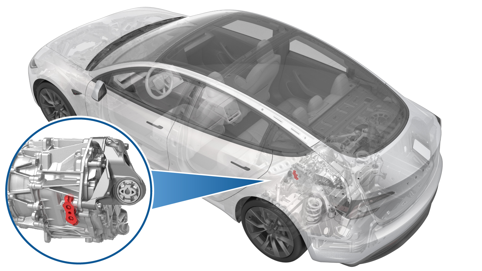
Cover - Phase Out - Rear Drive Unit (3DU) (Remove and Replace)
 Correction code
4001020042
FRT
0.84
NOTE: Unless
otherwise explicitly stated in the procedure, the above correction code and
FRT reflect all of the work required to perform this procedure, including
the linked procedures. Do
not stack correction codes unless explicitly told to do so.
NOTE: See Flat Rate
Times to learn more about FRTs and how
they are created. To provide feedback on FRT values, email ServiceManualFeedback@tesla.com.
NOTE: See Personal Protection
to make sure wearing proper PPE when performing the below procedure.
NOTE: See Ergonomic Precautions for safe and
healthy working practices.
Correction code
4001020042
FRT
0.84
NOTE: Unless
otherwise explicitly stated in the procedure, the above correction code and
FRT reflect all of the work required to perform this procedure, including
the linked procedures. Do
not stack correction codes unless explicitly told to do so.
NOTE: See Flat Rate
Times to learn more about FRTs and how
they are created. To provide feedback on FRT values, email ServiceManualFeedback@tesla.com.
NOTE: See Personal Protection
to make sure wearing proper PPE when performing the below procedure.
NOTE: See Ergonomic Precautions for safe and
healthy working practices.
- 1450875-00-A Kit, Inverter Leak Test Adapter, M3
- 1140501-00-A Pack Kit, Enclosure, Leak Test, HV Battery, Complete
- 1140311-00-A Lever Lock, HV Connector, Model 3
Only
technicians who have completed all required certification courses are permitted to
perform this procedure. Tesla recommends third party service provider technicians
undergo equivalent training before performing this procedure. For more information on
Tesla Technician requirements, or descriptions of the subject matter for third parties,
see HV Certification Requirements. Proper personal protective equipment (PPE) and insulating HV
gloves with a minimum rating of class 0 (1000V) must
be worn at all times a high voltage cable, busbar, or fitting is handled. Refer to Tech Note TN-15-92-003, High Voltage Awareness
Care Points
for additional safety
information.
Remove
- Raise and support the vehicle. See Raise Vehicle - 2 Post Lift.
- Remove the rear underhood apron. See Underhood Apron - Rear (Remove and Replace).
- Disconnect the LV power. See LV Power (Disconnect and Connect).
- Remove the 2nd row lower seat cushion. See Seat Cushion - 2nd Row (Remove and Replace).
- Perform Vehicle HV Disablement Procedure. See Vehicle HV Disablement Procedure (Test/Adjust).
- Remove the rear aero shield panel. See Panel - Aero Shield - Rear (Remove and Replace).
- Remove the rear HV battery skid plate. See Skid Plate - HV Battery - Rear (Remove and Replace).
-
Remove the bolt that
attaches the HV battery to rear drive unit harness bracket to the rear drive
unit inverter.
TIpUse of the following tool(s) is recommended:
- 10 mm socket
- Cordless hex driver
-
Remove the nut that attaches
the HV battery to rear drive unit harness bracket to the HV battery.
TIpUse of the following tool(s) is recommended:
- 10 mm magnetic deep nutsetter
- Cordless hex driver
-
Slide the release to unlock the HV battery rear drive unit connector handle of the rear drive unit to HV battery harness from the secured position.
-
Fully raise the handle on the HV battery rear drive unit connector.
- Disconnect the electrical connector that attaches the rear drive unit HV harness to the HV battery.
- Repeat step 10through step 12 on the other side of the rear drive unit HV harness.
-
Remove the label from the
phase out cover and discard it.
-
Remove the bolts (x2) that attach the phase out cover to the rear drive
unit.
TIpUse of the following tool(s) is recommended:
- External Torx Plus EP10
- 4 in extension
- Cordless Ratchet/Impact Driver
- Ratchet/torque wrench
-
Use a plastic trim tool to
remove the phase out cover from the vehicle.
Install
-
Install the bolts (x2) that
attach the phase out cover to the rear drive unit.
 14 Nm (10.3 lbs-ft)TIpUse of the following tool(s) is recommended:
- 10 mm deep socket
- 4 in extension
- Cordless Ratchet/Impact Driver
- Ratchet/torque wrench
- Perform the inverter air leak test. See Inverter Air Leak Test (Inspection).
-
Stick a new label to the phase out cover.
- Fully raise the handle on the electrical connector that attaches the rear drive unit HV harness to the rear drive unit.
-
Install the HV connector special tool
onto the electrical connector that attaches the rear drive unit HV harness to the rear
drive unit.
-
Use both hands to firmly connect the
electrical connector that attaches the rear drive unit HV harness to the rear drive
unit.
CAUTIONMake sure that the connector fits the header squarely and tightly, and that both retention pins enter the handle.
- Remove the HV connector special tool from the electrical connector that attaches the rear drive unit HV harness to the rear drive unit.
-
While pressing the electrical
connector that attaches the rear drive unit HV harness to the rear drive unit, fully
lower the handle.
CAUTIONMake sure that the handle does not bind as it is lowered.
-
Slide the release to lock
the electrical connector that attaches the rear drive unit HV harness to the
rear drive unit in the secured position.
-
Verify that the electrical
connector is fully seated, and compare both sides of the connector that it
is properly secured in place.
NoteAn improperly seated connector might lead to connector damage and rear drive unit problems later on.
- Repeat step 3through step 9 on the other side of the rear drive unit HV harness.
-
Install the nut that
attaches the HV battery to rear drive unit harness bracket to the HV
battery.10 Nm (7.4 lbs-ft)TIpUse of the following tool(s) is recommended:
- 10 mm socket
- Cordless hex driver
- Ratchet/torque wrench
-
Install the bolt that
attaches the HV battery to rear drive unit harness bracket to the rear drive
unit inverter.6 Nm (4.4 lbs-ft)TIpUse of the following tool(s) is recommended:
- 10 mm socket
- Cordless hex driver
- Ratchet/torque wrench
- Install the rear HV battery skid plate. See Skid Plate - HV Battery - Rear (Remove and Replace).
- Install the rear aero shield panel. See Panel - Aero Shield - Rear (Remove and Replace).
- Install the 2nd row lower seat cushion. See Seat Cushion - 2nd Row (Remove and Replace).
- Connect the LV power. See LV Power (Disconnect and Connect).
- Install the rear underhood apron. See Underhood Apron - Rear (Remove and Replace).
- Remove the vehicle from the 2 post lift. See Raise Vehicle - 2 Post Lift.