2026-02-27
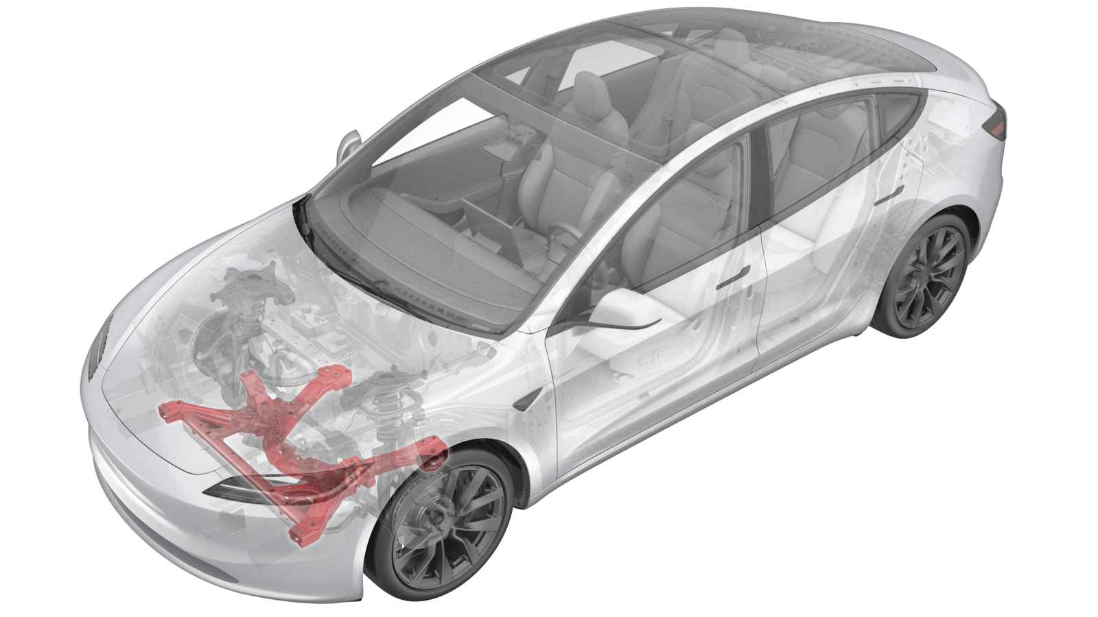
Subframe Assembly -Front (Remove and Replace)
 Correction code
3001010012
FRT
1.86
NOTE: Unless otherwise explicitly stated in the procedure, the correction code and FRT listed above reflect all of the work required to perform this procedure, including the linked procedures. Do not stack correction codes unless explicitly told to do so.
NOTE: See Flat Rate Times to learn more about FRTs and how they are created.
NOTE: See Personal Protection to make sure you
are wearing proper PPE when performing the procedure below.
NOTE: See Ergonomic Precautions for safe and healthy working practices.
Correction code
3001010012
FRT
1.86
NOTE: Unless otherwise explicitly stated in the procedure, the correction code and FRT listed above reflect all of the work required to perform this procedure, including the linked procedures. Do not stack correction codes unless explicitly told to do so.
NOTE: See Flat Rate Times to learn more about FRTs and how they are created.
NOTE: See Personal Protection to make sure you
are wearing proper PPE when performing the procedure below.
NOTE: See Ergonomic Precautions for safe and healthy working practices.
- 2025-07-23: Updated the torque of the bolts that attach the front lower lateral links to the front subframe to 190 Nm.
- 2024-04-17: Updated the front fascia to vehicle torque specification from 4 Nm to 2.5 Nm.
- 2024-04-11: Updated front lower lateral link to subframe torque specification.
Remove
- Put the vehicle on a 2-post lift.
- Open the LH front door and lower the LH front window.
-
Remove the LH and RH wheel caps.
NotePull the inner side of the adjacent 2 claws of the wheel cap to remove the wheel cap from the wheel.
Figure 1. LH shown, RH similar - Remove the underhood storage unit. See Underhood Storage Unit (Remove and Replace).
- Disconnect LV power. See LV Power (Disconnect and Connect).
-
Remove fasteners holding upper portion
of front fascia to vehicle
Note5x bolts, 10mm, 2.5 Nm
-
Remove and discard the bolt securing
the steering gear assembly to electric steering column
Note1x bolt, 13mm, 18 Nm
-
Slide the electric steering column
upward to remove it from the steering gear assembly
NoteMay need to wiggle or use dead blow to help separate
-
Disconnect the steering gear assembly
connectors
Note4x connectors
- Remove the LH and RH front wheels. See Wheel Assembly (Remove and Install).
-
Remove the front fascia. See Fascia - Front (Remove and Replace).
-
Remove the bolts (x2) that attach the
front end carrier to the LH front subframe crash can assembly, then repeat this step on
the RH side of the vehicle.
- Raise the vehicle. See Raise Vehicle - 2 Post Lift.
-
Remove and discard the nut that
attaches the LH front tie rod end to the LH front knuckle.
- Remove the LH front tie rod end from the LH front knuckle.
-
Remove and discard the nut that
attaches the stabilizer bar link to the LH front stabilizer bar.
-
Move the LH front stabilizer bar link
aside.
NoteMove the stabilizer bar up/down to get the correct angle to remove the end link.
- Repeat step 14 through step 17 on the RH side of the vehicle.
-
Release the clip that attaches the
front drive unit bypass hose to the front subframe.
-
Remove the bolt and nut that attach
the LH front lower compliance link to the front subframe.
-
Remove and discard the bolts (x2) that
attach the LH front lower lateral link to the front subframe.
-
Remove the nut and bolt that attach
the LH strut to the LH front lower lateral link.
- Repeat step 20 through step 22 on the RH side of the vehicle.
- Position the front subframe lifting tool beneath the front subframe.
- Attach an air hose to the front subframe lifting tool.
- With an assistant, raise the front subframe lifting tool to support the front subframe.
-
Loop the straps over the front
subframe, hook the ends of the straps to the metal rings, and then pull the straps tight
to restrain the subframe to the front subframe lifting tool.
NoteLower the vehicle to give more slack to connect the straps to the rings, if necessary.
-
Remove and discard the bolt that
attaches the LH mid mount to the body, then repeat this step on the RH side.
-
Remove and discard the bolts (x2) that
attach the front portion of the front subframe to the body.
-
Remove and discard the smaller bolts
(x2) that attach the rear portion of the front subframe to the body.
-
Remove and discard the larger bolts
(x2) that attach the rear portion of the front subframe to the body.
- Lower the front subframe assembly from the vehicle.
- Disconnect the air hose from the front subframe lifting tool.
- Move the front subframe lifting tool from under the vehicle.
-
Remove the front bolts (x2) that
attach the steering gear assembly to the front subframe.
Figure 2. LH shown, RH similar -
Remove that the rear bolts (x2) that
attach the steering gear assembly to the front subframe.
-
Remove the steering gear assembly from
the front subframe.
-
With an assistant, remove and discard
the LH nuts (x2) that attach the front stabilizer bar to the front subframe, then repeat
this step on the RH side.
Figure 3. LH shown, RH similar -
Remove the bolts (x2) that attach the
front subframe to the LH front subframe crush can assembly, then repeat this step on the
RH side.
Figure 4. LH shown, RH similar -
With an assistant, remove the front
subframe from the front subframe lifting tool.
Install
-
With an assistant, position the front
subframe to the front subframe lifting tool.
NoteMake sure the 2 guides align.
-
Hand-tighten the bolts (x2) that
attach the LH front subframe crush can assembly to the front subframe, then repeat this
step on the RH side.
Figure 5. LH shown, RH similar -
With an assistant, install and mark
the LH nuts (x2) that attach the front stabilizer bar to the front subframe, then repeat
this step on the RH side.
 35 Nm (25.8 lbs-ft)
Figure 6. LH shown, RH similar -
Position the steering gear assembly to
the front subframe for installation.
-
Hand-tighten the rear bolts (x2) that
attach the steering gear assembly to the front subframe.
-
Hand-tighten the front bolts (x2) that
attach the steering gear assembly to the front subframe.
-
Torque the front bolts that attach the
steering gear assembly to the front subframe.47 Nm (34.7 lbs-ft)
-
Torque the rear bolts that attach the
steering gear assembly to front subframe.75 Nm (55.3 lbs-ft)
-
Position the front subframe lifting
tool and front subframe under the vehicle for installation.
- Connect an air hose to the front subframe lifting tool.
-
With an assistant, raise the front
subframe lifting tool until the front subframe and body meet.
NoteMake sure to line up the rear locator pins on the subframe.WarningThe video(s) included in this procedure are meant as an overview for supplemental purposes only. Follow all of the steps listed in the procedure to avoid damage to components and/or personal injury.
-
Hand-tighten the larger bolts (x2)
that attach the rear portion of the front subframe to the body.
-
Hand-tighten the smaller bolts (x2)
that attach the rear portion of the front subframe to the body.
-
Hand-tighten the bolts (x2) that
attach the front portion of the front subframe to the body.
-
Hand-tighten the bolt that attaches
the LH mid mount to the body, then repeat this step on the RH side.
-
Hand-tighten the bolts (x2) that
attach the front end carrier to the LH front subframe crash can assembly, then repeat
this step on the RH side of the vehicle.
-
Torque the larger bolts (x2) that
attach the rear portion of the front subframe to body.125 Nm (92.2 lbs-ft)
-
Torque the smaller bolts (x2) that
attach the rear portion of the front subframe to the body.50 Nm (36.9 lbs-ft)
-
Torque the bolts (x2) that attach the
front portion of the front subframe to the body.72 Nm (53.1 lbs-ft)
-
Torque the bolt that attaches the LH
mid mount to the body, then repeat this step on the RH side.50 Nm (36.9 lbs-ft)
-
Torque the bolts (x2) that attach the
front subframe to the LH front subframe crush can assembly, then repeat this step on the
RH side.53 Nm (39.1 lbs-ft)
-
Torque the bolts (x2) that attach the
front end carrier to the LH front subframe crash can assembly, then repeat this step on
the RH side of the vehicle.16 Nm (11.8 lbs-ft)
- Lower the front subframe lifting tool from the vehicle.
- Disconnect the air hose from the front subframe lifting tool.
- Remove the front subframe lifting tool from under the vehicle.
-
Hand-tighten the nut and bolt that
attach the LH strut to the LH front lower lateral link.
-
With an assistant, hand-tighten the
new bolts (x2) that attach the LH front lower lateral link to the front subframe.
NoteBolt PN: 2123635-00-A
-
With an assistant, install the bolt
and nut that attach the LH front lower compliance link to the front subframe.115 Nm (84.8 lbs-ft)
-
Torque the bolts (x2) that attach the
LH front lower lateral link to the front subframe.190 Nm (140.1 lbs-ft)
- Repeat step 26 through step 29 on the RH side of the vehicle.
- Lower the vehicle.
-
Position the LH front stabilizer bar
link assembly to the front stabilizer bar.
NotePull down on the sway bar to allow the end link to engage.
-
Install the nut that attaches the
front stabilizer bar link to the LH front stabilizer bar.98 Nm (72.3 lbs-ft)
- Position the LH front tie rod end to the LH front knuckle.
-
Install the nut that attach the LH tie
rod end to the LH front knuckle.180 Nm (132.7 lbs-ft)
- Repeat step 32 through step 35 on the RH side of the vehicle.
-
Install the clip that attaches the
front drive unit bypass hose to the front subframe.
-
Install the lug nuts (x5) that attach
the hub jack adapter onto the LH front hub.
-
Raise and adjust the support stand to
the ride height.
-
Measure from the bottom of the fender
to the center of the axle to make sure the LH suspension is set close to the ride height
(423mm).
-
Torque the nut and bolt that attach
the LH strut to the LH front lower lateral link.106 Nm (78.2 lbs-ft)
-
Remove the support stand from
underneath the LH front suspension.
-
Remove the lug nuts (x5) that attach
the hub jack adapter to the LH front hub.
NoteGently tap with a dead blow to aid in removal.
- Install the LH front wheel. See Wheel Assembly (Remove and Install).
- Repeat step 38 through step 44 on the RH side of the vehicle.
- Lower the vehicle fully.
-
Slide the intermediate shaft assembly
downward to install it to the steering gear assembly
NoteEnsure the intermediate shaft is aligned and fully seated, if necessary, align the shaft to steering gear.
-
Install new bolt (P/N:1111523-00-A)
that attaches the intermediate shaft assembly to the steering gear assembly.18 Nm (13.3 lbs-ft)
- Connect the steering gear assembly electrical connectors (x4).
- Install the front fascia. See Fascia - Front (Remove and Replace).
- Install the underhood storage unit. See Underhood Storage Unit (Remove and Replace).
- Install the LH and RH wheel caps.
- Remove the vehicle from the 2 post lift. See .
- Refer to the Alignment Requirement tables to determine whether an EPAS alignment check (EC) or four wheel alignment check (AC) is necessary. If performed, add the alignment check/adjust as a separate activity. See Alignment Requirement - Suspension.