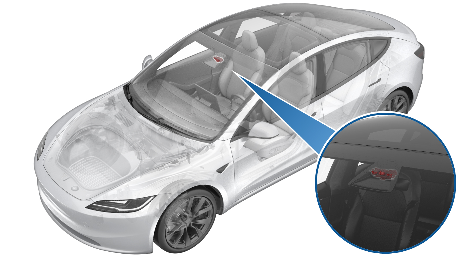
Camera - Forward Facing (Remove and Replace)
 Correction code
1723020012
FRT
0.42
NOTE: Unless
otherwise explicitly stated in the procedure, the above correction code and
FRT reflect all of the work required to perform this procedure, including
the linked procedures. Do
not stack correction codes unless explicitly told to do so.
NOTE: See Flat Rate
Times to learn more about FRTs and how
they are created. To provide feedback on FRT values, email ServiceManualFeedback@tesla.com.
NOTE: See Personal Protection
to make sure wearing proper PPE when performing the below procedure.
NOTE: See Ergonomic Precautions for safe and
healthy working practices.
- 2025-06-12: Added the LV power connect/disconnect steps, and added the step of cleaning the camera calibration.
Torque Specifications
| Description | Torque Value | Recommended Tools | Reuse/Replace | Notes |
|---|---|---|---|---|
| Screws (x4) that attach the mount plate to the forward facing camera and the windshield bracket |
 1 Nm (.7 lbs-ft) |
|
Replace | 1879037-01-E |
Remove
- Place the vehicle in Service Mode by using the touchscreen. See Service Mode.
- Disconnect the LV battery power. See LV Power (Disconnect and Connect).
- Remove the lower camera cover. See Camera Cover - Lower (Remove and Replace).
- Remove the rear view mirror. See Mirror - Rear View (Remove and Replace).
-
Remove the upper camera
cover. See Camera Cover - Upper (Remove and Replace).
NoteNo need to remove the interior camera from the upper camera cover.
- Remove the rear view mirror glare shield. See Glare Shield - Front Camera (Remove and Replace).
-
Remove and discard the
screws (x4) that attach the mount plate to the forward facing camera and the
windshield bracket, and then remove the mount plate from the vehicle.
TIpUse of the following tool(s) is recommended:
- Torx T10 bit
-
Disconnect the electrical
harness from the forward facing camera connectors, and then remove the
forward facing camera from the vehicle.
Install
-
Clean the inner windshield
camera viewing area with a clean microfiber cloth and glass cleaner. Let the
windshield fully dry before continuing.
CAUTIONVerify that the windshield has no stains or leftover residue. Otherwise, Autopilot features may be hindered.
-
Install the forward facing camera to the windshield bracket, and then
connect the electrical harness to the forward facing camera
connectors.
-
Install the mount plate to
the forward facing camera and the windshield bracket, and then install new
screws (x4) that attach the mount plate to the camera and bracket.
 1 Nm (.7 lbs-ft)TIpUse of the following tool(s) is recommended:
- Torx T10 bit
- Install the rear view mirror glare shield. See Glare Shield - Front Camera (Remove and Replace).
-
Install the upper camera
cover. See Camera Cover - Upper (Remove and Replace).
NoteNo need to install the interior camera to the upper camera cover.
- Connect the LV battery power. See LV Power (Disconnect and Connect).
-
Clean the camera calibration.
- Tap .
-
Select ForwardFacing in the
Camera Selection
drop list. - Tap Run, and then allow the routine to complete.
- Unlock the vehicle gateway. See Gateway Unlock.
- Locally connect a laptop with Toolbox 3 to the vehicle. See Toolbox (Connect and Disconnect).
-
In Toolbox, perform the following
steps.
- Click the Actions tab, type "DAS" into the search field, click PROC_DAS_X_ENTER-CALIBRATION-MODEvia Toolbox: (link), click Run, and allow the routine to complete.
- Click the Actions tab, type "Front Camera" into the search field, click PING-HTTP_DAS_X_MAIN-CAMERA-SCRIPTvia Toolbox: (link), change the timeout to 100, click Run, and allow the routine to complete.
- Click the Actions tab, type "Fisheye Camera" into the search field, click PING-HTTP_DAS_X_FISHEYE-CAMERA-SCRIPTvia Toolbox: (link), change the timeout to 100, click Run, and allow the routine to complete.
- Click the Actions tab, type "DAS" into the search field, click PROC_DAS_X_EXIT-CALIBRATION-MODEvia Toolbox: (link)via Service Mode Plus: Driver Assist ➜ Cameras ➜ Exit Factory Calibration Mode, click Run, and allow the routine to complete.
- Perform the forward facing camera pitch verification. See Camera - Forward Facing (Pitch Verification) (Test/Adjust).
- Install the rear view mirror. See Mirror - Rear View (Remove and Replace).
- Install the lower camera cover. See Camera Cover - Lower (Remove and Replace).
- Disable Service Mode. See Service Mode.
-
Inform the customer that the
vehicle needs to be driven by the customer to complete the calibration
procedure.
NoteSelf-calibration can take up to 100 miles (160 km) of manual driving, depending upon the road type and condition. Until self-calibration is complete, the message "Autopilot Features Currently Unavailable: Manual Driving Required While Camera Is Calibrating" is displayed if an attempt is made to engage an Autopilot feature.