2025-06-04
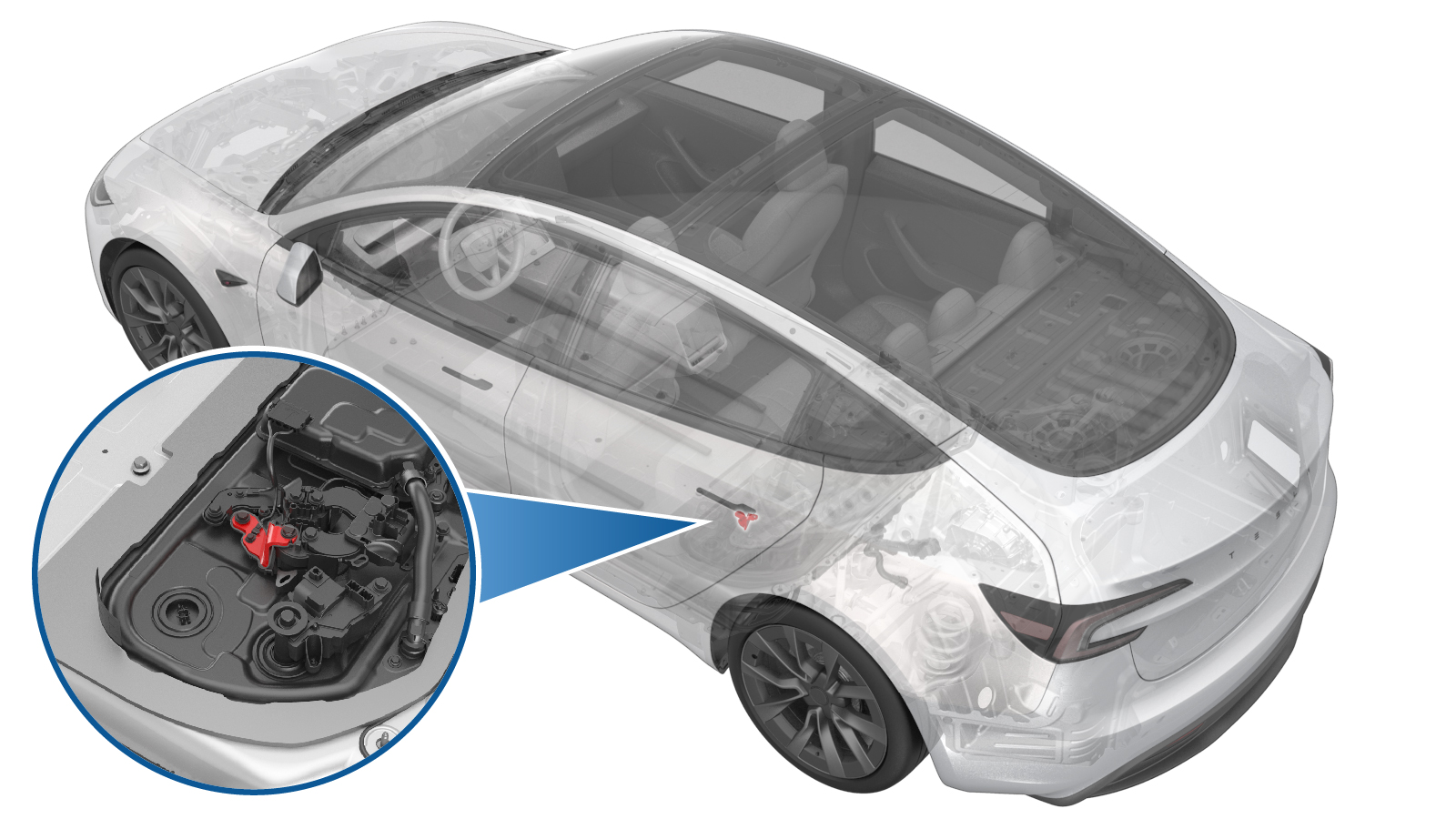
Busbar - Fast Charge - Input - Positive (Remove and Replace)
 Correction code
1630010052
FRT
1.44
NOTE: Unless otherwise explicitly stated in the procedure, the correction code and FRT listed above reflect all of the work required to perform this procedure, including the linked procedures. Do not stack correction codes unless explicitly told to do so.
NOTE: See Flat Rate Times to learn more about FRTs and how they are created.
NOTE: See Personal Protection to make sure you
are wearing proper PPE when performing the procedure below.
NOTE: See Ergonomic Precautions for safe and healthy working practices.
Correction code
1630010052
FRT
1.44
NOTE: Unless otherwise explicitly stated in the procedure, the correction code and FRT listed above reflect all of the work required to perform this procedure, including the linked procedures. Do not stack correction codes unless explicitly told to do so.
NOTE: See Flat Rate Times to learn more about FRTs and how they are created.
NOTE: See Personal Protection to make sure you
are wearing proper PPE when performing the procedure below.
NOTE: See Ergonomic Precautions for safe and healthy working practices.
- 2025-06-04: Added instruction to zero adjust the Hioki resistance meter prior to measurement.
Torque Specifications
| Description | Torque Value | Recommended Tools | Reuse/Replace | Notes |
|---|---|---|---|---|
| Bolt that attaches the busbar cover access door |
 9 Nm (6.6 lbs-ft) |
|
Reuse | |
| Bolts (x2) that attach the charge port busbar kit to the HV header |
9 Nm (6.6 lbs-ft) |
|
Reuse | |
| Patch bolts (x2) that attach the DC link side negative and positive fast charge busbars to the fast charge contactor |
15 Nm (11.1 lbs-ft) - 180 degrees 5 Nm (3.7 lbs-ft) + 60 degrees |
|
Replace | |
| Patch bolt that attaches the inlet side negative fast charge busbar and the negative DC input assembly busbar |
15 Nm (11.1 lbs-ft) - 180 degrees 5 Nm (3.7 lbs-ft) + 60 degrees |
|
Replace | |
| Patch bolt that attaches the inlet side positive fast charge busbar to the positive DC input assembly busbar |
15 Nm (11.1 lbs-ft) - 180 degrees 5 Nm (3.7 lbs-ft) + 60 degrees |
|
Replace | |
| Bolts (x4) that attach the DC input busbar assembly to the Ancillary Bay |
10 Nm (7.4 lbs-ft) |
|
Replace | |
| Bolts (x2) that attach the fast charge assembly to the Ancillary Bay |
5.5 Nm (4.1 lbs-ft) |
|
Reuse | |
| Patch bolt that attaches the inlet side positive fast charge busbar to the fast charge contactor |
15 Nm (11.1 lbs-ft) - 180 degrees 5 Nm (3.7 lbs-ft) + 60 degrees |
|
Replace |
Remove
- Open all the doors and lower all the windows.
- Disconnect the LV power. See LV Power (Disconnect and Connect).
- Remove the LH 2nd row seat cushion bracket. See Bracket - Edge Support - Seat Cushion - 2nd Row - LH (Remove and Replace).
- Perform the Vehicle HV Disablement Procedure. See Vehicle HV Disablement Procedure (Test/Adjust).
-
Remove the bolt that secures the
busbar cover access door.
TIpUse of the following tool(s) is recommended:
- 10 mm 12-point deep socket
-
Remove bolts (x2) that secure the
charge port busbar kit to the HV header.
TIpUse of the following tool(s) is recommended:
- 10 mm 12-point deep socket
-
Release the AC charge port inlet harness clip.
-
Lift the busbar kit connector and
shift the rear end of the busbar assembly upward to remove the aluminum connector
housing from the HV header.
-
Position the charge port busbar
connector on the cross-member in front of the ancillary bay for access.
- Remove the ancillary bay cover. See Ancillary Bay Cover (Remove and Replace).
- Remove the pyrotechnic battery disconnect. See Pyro Disconnect - HV Battery (Remove and Replace).
- Remove the HV battery negative contactor. See Pack Contactor - High Voltage - Negative (Remove and Replace).
-
Press the tabs on both sides by hand,
and lift the connector upwards to disconnect the LV fast charge contactor
connector.
-
Disconnect the PCS to AC harness
connector.
NotePull the locking tab upward to release. Use a plastic trim tool to help lift the connector upward as necessary.
-
Release the locking tab, and then disconnect the AC filter harness from the FC
contactor cover.
-
Release harness clips (x2) from the FC contactor cover, and then move the wiring
harness aside around the FC contactor cover.
-
Remove the LH Ancillary Bay terminal cover.
-
Remove and discard the patch bolts
(x2) that secure the DC link side negative and positive fast charge busbars.
TIpUse of the following tool(s) is recommended:
- 13 mm socket
- Torque wrench with angle measurement
Figure 1. Negative fast charge port busbar bolt Figure 2. Positive fast charge port busbar bolt -
Disconnect the megaharness connector from the DC input assembly.
-
Remove the insulator for DC input assembly to both inlet side fast charge
busbars.
-
Remove and discard the patch bolt that secures the inlet side negative fast charge
busbar and the negative DC input assembly busbar.
TIpUse of the following tool(s) is recommended:
- 13 mm socket
- Torque wrench with angle measurement
-
Remove and discard the patch bolt that secures the inlet side positive fast charge
busbar and the positive DC input assembly busbar.
TIpUse of the following tool(s) is recommended:
- 13 mm socket
- Torque wrench with angle measurement
-
Remove and discard the bolts (x4) that secure the DC input busbar assembly to
Ancillary Bay, and then remove the DC input busbar assembly from Ancillary Bay.
TIpUse of the following tool(s) is recommended:
- External Torx E10 5-Lobe
-
Remove the bolts (x2) that secure the
fast charge assembly to Ancillary Bay.
TIpUse of the following tool(s) is recommended:
- 10 mm socket
-
Remove the fast charge assembly from Ancillary Bay.
-
Remove and discard the fast charge insulator cover from the fast charge
assembly.
NotePull the insulator cover upward to release it from the clips (x8) and alignment pin.WarningThe video(s) included in this procedure are meant as an overview for supplemental purposes only. Follow all of the steps listed in the procedure to avoid damage to components and/or personal injury.
-
Remove and discard the patch bolt that
attaches the positive inlet fast charge busbar to the fast charge contactor, and then
remove the positive inlet fast charge busbar from the fast charge contactor.
TIpUse of the following tool(s) is recommended:
- 13 mm socket
- Torque wrench with angle measurement
Install
-
Install new patch bolt that attaches
the positive inlet fast charge busbar to the fast charge contactor.15 Nm (11.1 lbs-ft) - 180 degrees5 Nm (3.7 lbs-ft) + 60 degreesNoteTighten the bolt to 15 Nm, back off 180 degrees, then torque to 5 Nm + 60 degrees. Mark after torque.TIpUse of the following tool(s) is recommended:
- 13 mm socket
- Torque wrench with angle measurement
-
Install new fast charge insulator cover to the fast charge assembly.
-
Position the fast charge assembly to
the ancillary bay for installation.
-
Install the bolts (x2) that secure the
fast charge assembly to the ancillary bay.5.5 Nm (4.1 lbs-ft)TIpUse of the following tool(s) is recommended:
- 10 mm socket
-
Install the DC input busbar assembly
to the ancillary bay.
NoteEnsure the seal is not damaged and seated properly.
-
Install new bolts (x4) that secure the
DC input busbar assembly to the ancillary bay.10 Nm (7.4 lbs-ft)NoteMark after torque.TIpUse of the following tool(s) is recommended:
- External Torx E10 5-Lobe
-
Install new patch bolt that secures
the inlet side negative fast charge busbar and the negative DC input assembly
busbar.15 Nm (11.1 lbs-ft) - 180 degrees5 Nm (3.7 lbs-ft) + 60 degreesNoteTighten the bolt to 15 Nm, back off 180 degrees, then torque to 5 Nm + 60 degrees. Mark after torque.TIpUse of the following tool(s) is recommended:
- 13 mm socket
- Torque wrench with angle measurement
-
Install new patch bolt that secures
the inlet side positive fast charge busbar and the positive DC input assembly
busbar.15 Nm (11.1 lbs-ft) - 180 degrees5 Nm (3.7 lbs-ft) + 60 degreesNoteTighten the bolt to 15 Nm, back off 180 degrees, then torque to 5 Nm + 60 degrees. Mark after torque.TIpUse of the following tool(s) is recommended:
- 13 mm socket
- Torque wrench with angle measurement
- Perform zero adjust to Hioki meter. See Resistance Meter (Zero Adjust).
-
Perform Hioki resistance test at both
HV joints of the DC input assembly busbar.
NoteThe resistance should be 60 𝜇Ω or less. Test from the negative fast charge busbar to the negative DC input busbar, and from the positive fast charge busbar to the positive DC input. busbar.
-
Install the insulator for DC input assembly to both inlet side fast charge
busbars.
-
Connect the megaharness connector to the DC input assembly.
-
Install new patch bolt that secures
the DC link side positive fast charge busbar.15 Nm (11.1 lbs-ft) - 180 degrees5 Nm (3.7 lbs-ft) + 60 degreesNoteTighten the bolt to 15 Nm, back off 180 degrees, then torque to 5 Nm + 60 degrees. Mark after torque.NoteUse of the following tool(s) is recommended:
- 13 mm socket
- Torque wrench with angle measurement
-
Perform Hioki resistance test at the
positive HV joint of the DC link side fast charge busbar.
NoteThe resistance should be 25 𝜇Ω or less.
-
Install new patch bolt that secures
the DC link side negative fast charge busbar.15 Nm (11.1 lbs-ft) - 180 degrees5 Nm (3.7 lbs-ft) + 60 degreesNoteTighten the bolt to 15 Nm, back off 180 degrees, then torque to 5 Nm + 60 degrees. Mark after torque.NoteUse of the following tool(s) is recommended:
- 13 mm socket
- Torque wrench with angle measurement
-
Perform Hioki impedance test at the negative HV joint of the DC link side fast charge
busbar.
NoteThe resistance should be 55 𝜇Ω or less.
-
Install the LH Ancillary Bay terminal cover.
-
Install the harness clips (x2) to the FC contactor cover.
-
Connect the LV fast charge connector.
-
Secure the locking tab to install the AC filter harness to the FC contactor
cover.
-
Connect the PCS to AC harness connector.
NotePush the connector downward, and then push the locking tab downward to install the connector. Make sure the connector is fully seated.
- Install the HV battery negative contactor. See Pack Contactor - High Voltage - Negative (Remove and Replace).
- Install the pyrotechnic battery disconnect. See Pyro Disconnect - HV Battery (Remove and Replace).
-
Position the Ancillary Bay cover to HV battery for installation.
NoteEnsure all accessible insulators are present.
-
Use IPA wipes to clean the HV
connector contact surface and the busbar HV connector contact surface of the residual
Penetrox.
NoteAllow 1 minute dry time for each surface. The new busbar comes with the penetrox applied to the HV connector. It is necessary to clean the HV connector during the re-use of the busbar.
- Apply 2 drops of Penetrox A-13 about 5mm in diameter to either side of the hole on both leads on the HV connector joints, and then spread the liquid evenly until the contact surface is fully covered.
-
Position the busbar kit connector and
lower it onto the HV header.
NoteShift the rear end of the busbar assembly upward to help ease installation. If excessive force is required to seat the busbar, they may have been bent. Inspect for damage and replace if necessary.
-
Install the AC charge port inlet harness clip.
-
Install the bolts (x2) that secure the
charge port busbar kit to the HV header.9 Nm (6.6 lbs-ft)Use of the following tool(s) is recommended:
- 10 mm 12-point deep socket
-
Perform Hioki resistance test at each
HV joint from the HV busbar lead to the bolt head.
NoteThe acceptable resistance is between 0.050 mΩ (50 μΩ) and 0.195 mΩ (195 μΩ).
- If the resistance is greater than 0.195 mΩ (195 μΩ), there is too much resistance in the High Voltage joint. Remove the fastener, clean areas with isopropyl alcohol, install fastener back and test again.
- If the resistance is lower than 0.050 mΩ (50 μΩ), reposition the probes and measure again.
- If the resistance is repeatedly between 0.00 mΩ and 0.050 mΩ (50 μΩ), Hioki test passed, proceed to the next step.
-
Install the bolt that secures the
busbar cover access door.9 Nm (6.6 lbs-ft)TIpUse of the following tool(s) is recommended:
- 10 mm 12-point deep socket
-
Install the Ancillary Bay cover. See Ancillary Bay Cover (Remove and Replace).
NoteBefore installing the ancillary bay cover, inspect the ancillary bay cover seal and confirm there is no visual damage. If the seal is torn and/or delaminated, replace the ancillary bay cover.
- Install the LH 2nd row seat cushion bracket. See Bracket - Edge Support - Seat Cushion - 2nd Row - LH (Remove and Replace).
- Connect the LV power. See LV Power (Disconnect and Connect).
- Raise all the windows and close all the doors.