2025-04-11
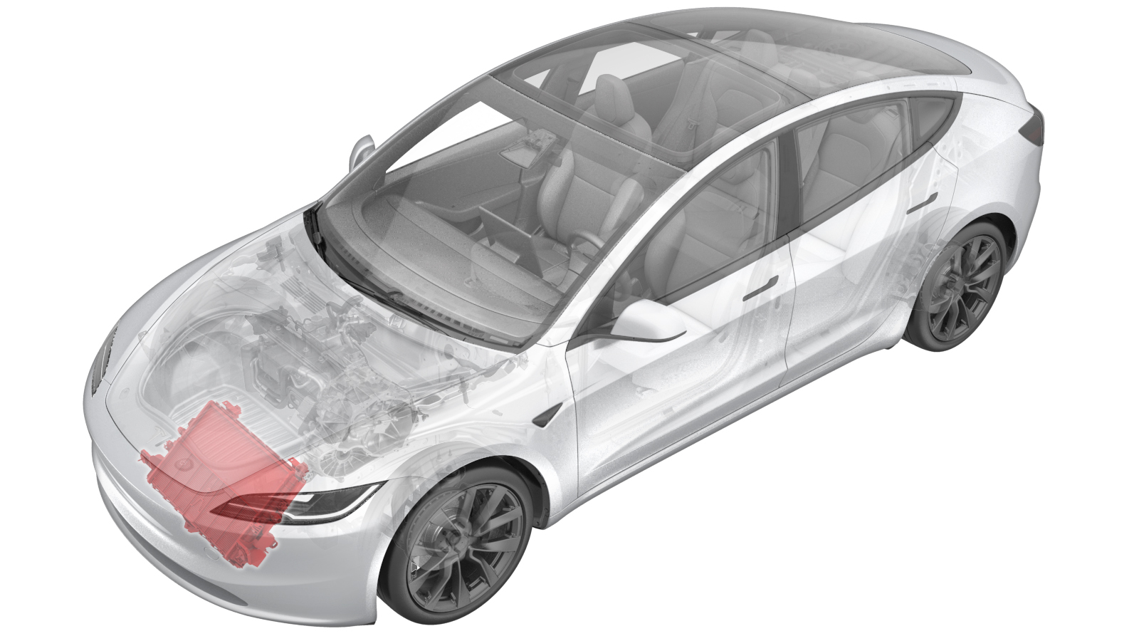
Cooling Fan Module (Remove and Replace)
 Correction code
1830036012
FRT
0.66
NOTE: Unless otherwise explicitly stated in the procedure, the above correction code and FRT reflect all of the work required to perform this procedure, including the linked procedures. Do not stack correction codes unless explicitly told to do so.
NOTE: See Flat Rate Times to learn more about FRTs and how they are created. To provide feedback on FRT values, email ServiceManualFeedback@tesla.com.
NOTE: See Personal Protection to make sure wearing proper PPE when performing the below procedure.
NOTE: See Ergonomic Precautions for safe and healthy working practices.
Correction code
1830036012
FRT
0.66
NOTE: Unless otherwise explicitly stated in the procedure, the above correction code and FRT reflect all of the work required to perform this procedure, including the linked procedures. Do not stack correction codes unless explicitly told to do so.
NOTE: See Flat Rate Times to learn more about FRTs and how they are created. To provide feedback on FRT values, email ServiceManualFeedback@tesla.com.
NOTE: See Personal Protection to make sure wearing proper PPE when performing the below procedure.
NOTE: See Ergonomic Precautions for safe and healthy working practices.
Remove
- Raise and support the vehicle. See Raise Vehicle - 2 Post Lift.
- Remove the rear underhood apron. See Underhood Apron - Rear (Remove and Replace).
- Unlock the vehicle gateway. See Gateway Unlock.
- On the touchscreen, touch and select Run to start the "Start Thermal Fluid Fill/Drain (Coolant Only)" routine.
- Disconnect the LV power. See LV Power (Disconnect and Connect).
- Remove the cabin intake duct. See Assembly - Fresh Air Gutter - HVAC (Remove and Replace).
- Remove the access panel. See Cover - Hood Latch (Remove and Replace).
- Remove the underhood storage unit. See Underhood Storage Unit (Remove and Replace).
-
Carefully remove the ambient
temperature sensor cover from the active grille shutter.
-
Disconnect the ambient
temperature sensor electrical connector.
-
Release the connector lock,
and then disconnect the active grille shutter actuator electrical
connector.
CAUTIONDo not push down on the red tab. Pull the red tab to release the connector lock.
-
Remove the bolts (x2) that
attach the underhood storage unit reinforcement bracket to the cooling fan,
and then slide the bracket rearward for clearance.
TIpUse of the following tool(s) is recommended:
- 10 mm socket
- 2 in extension
- Cordless hex driver
- Remove the front aero shield panel. See Panel - Aero Shield - Front (Remove and Replace).
- Remove the front valance. See Valance - Front Fascia (Remove and Replace).
- Place a coolant drain container underneath the LH front of the vehicle.
-
Release the spring clip,
disconnect the radiator inlet hose from the radiator, and then plug the hose
and radiator.
- Place the coolant drain container underneath the RH front of the vehicle.
-
Release the spring clip,
disconnect the radiator outlet hose from the radiator, and then plug the
hose and radiator.
- Remove the coolant drain container from underneath the vehicle.
-
Disconnect the cooling fan
module electrical connector.
-
Remove the LH bolt that
attaches the bottom of the condenser fan module to the ankle catcher, then
repeat this step on the RH side.
NoteHold the condenser fan module up to ease removal of the bolts.TIpUse of the following tool(s) is recommended:
- 8 mm socket
- Cordless Ratchet/Impact Driver
Figure 1. LH shown, RH similar -
Remove the cooling fan
module assembly from the vehicle.
Install
- With assistance, position the cooling fan module assembly into the vehicle, and then loosely install the bolts that attach the module assembly to the vehicle.
-
Torque the LH bolt that attaches the bottom of the condenser fan module to
the ankle catcher, then repeat this step on the RH side.
 10 Nm (7.4 lbs-ft)TIpUse of the following tool(s) is recommended:
- 8 mm socket
- Cordless Ratchet/Impact Driver
- Ratchet/torque wrench (for installation only)
Figure 2. LH shown, RH similar -
Remove the plugs from the
radiator and radiator outlet hose, immediately connect the radiator outlet
hose to the radiator, and then fasten the clip.
NotePerform a push-pull-push test on the fittings to make sure that they are secure.
-
Remove the plugs from the
radiator and radiator inlet hose, immediately connect the radiator inlet
hose to the radiator, and then fasten the clip.
NotePerform a push-pull-push test on the fittings to make sure that they are secure.
-
Connect the cooling fan
module electrical connector, and then engage the connector lock.
- Install the front valance. See Valance - Front Fascia (Remove and Replace).
- Install the front aero shield panel. See Panel - Aero Shield - Front (Remove and Replace).
- Lower the vehicle fully.
-
Position the underhood
storage unit reinforcement bracket onto the cooling fan, and then install
the bolts (x2) that attach the bracket to the fan.16 Nm (11.8 lbs-ft)TIpUse of the following tool(s) is recommended:
- 10 mm socket
- Cordless Ratchet/Impact Driver
- Ratchet/torque wrench (for installation only)
-
Connect the ambient
temperature sensor electrical connector.
-
Install the ambient
temperature sensor cover to the active grille shutter.
-
Connect the active grille shutter actuator electrical connector, then
engage the connector lock.
- Remove the coolant bottle cap, and then fill the coolant to the "Max" line.
- Connect the LV power. See LV Power (Disconnect and Connect).
-
On the touchscreen, perform the following steps.
-
Inspect the coolant level
and top off as necessary, and then install the coolant bottle cap.
NoteEnsure that the coolant level is at the "Max" line.
- On the touchscreen, touch and select Run to start the "Thermal System Performance Test" routine, and allow the routine to complete.
- On the touchscreen, touch and select Run to start the "HVAC System Performance Test" routine, and allow the routine to complete.
- Disable Service Mode. See Service Mode.
- Install the underhood storage unit. See Underhood Storage Unit (Remove and Replace).
- Install the access panel. See Cover - Hood Latch (Remove and Replace).
- Install the fresh air duct. See Fresh Air Intake - HVAC (Remove and Replace).
- Install the rear underhood apron. See Underhood Apron - Rear (Remove and Replace).