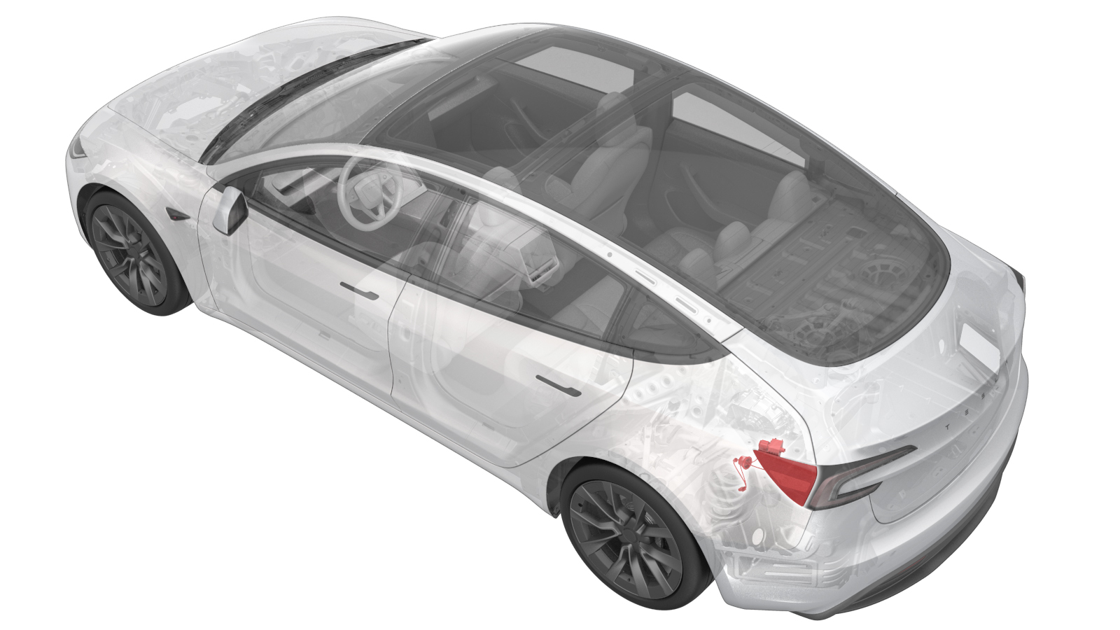
Door Assembly - Charge Port (EU) (Remove and Replace)
 Correction code
4401010222
FRT
0.66
NOTE: Unless otherwise explicitly stated in the procedure, the correction code and FRT listed above reflect all of the work required to perform this procedure, including the linked procedures. Do not stack correction codes unless explicitly told to do so.
NOTE: See Flat Rate Times to learn more about FRTs and how they are created.
NOTE: See Personal Protection to make sure you
are wearing proper PPE when performing the procedure below.
NOTE: See Ergonomic Precautions for safe and healthy working practices.
Correction code
4401010222
FRT
0.66
NOTE: Unless otherwise explicitly stated in the procedure, the correction code and FRT listed above reflect all of the work required to perform this procedure, including the linked procedures. Do not stack correction codes unless explicitly told to do so.
NOTE: See Flat Rate Times to learn more about FRTs and how they are created.
NOTE: See Personal Protection to make sure you
are wearing proper PPE when performing the procedure below.
NOTE: See Ergonomic Precautions for safe and healthy working practices.
Equipment:
- 1076921-00-A FLUKE DIGITAL MULTIMETER 1587
Only
technicians who have completed all required certification courses are permitted to
perform this procedure. Tesla recommends third party service provider technicians
undergo equivalent training before performing this procedure. For more information on
Tesla Technician requirements, or descriptions of the subject matter for third parties,
see HV Certification Requirements. Proper personal protective equipment (PPE) and insulating HV
gloves with a minimum rating of class 0 (1000V) must
be worn at all times a high voltage cable, busbar, or fitting is handled. Refer to Tech Note TN-15-92-003, High Voltage Awareness
Care Points
for additional safety
information.
Remove all jewelry (watches, bracelets, rings, necklaces, earrings, ID tags, piercings, etc.) from your person, and all objects (keys, coins, pens, pencils, tools, fasteners, etc.) from your pockets before performing any procedure that exposes you to high voltage.
Proper personal protective equipment (PPE) is required to perform this procedure:
- High voltage insulating gloves
- Leather glove protectors
- High voltage glove tester
- Safety glasses
- Electrical hazard rated safety shoes
A glove inflator is the only recommended way to test HV gloves. Both HV gloves must pass testing before beginning this procedure. If either glove does not pass the air check, discard the pair.
Make sure that the HV gloves are not expired. HV gloves can be used up to 12 months after the testing date printed on the glove, but only 6 months after first use even if the gloves are still within the 12-month period.
Remove
- Apply masking tape around the charge port area.
- Remove the charge port (EU). See Charge Port (CCS) (Remove and Replace).
-
Disconnect the low voltage
electrical connector from the charge port ECU.
-
Release the charge port door
harness grommet from the body.
-
Release the lower clips (x2)
that attach the charge port door to the vehicle.
NoteRelease the bottom clips, and then push the bottom of charge port door out.
-
Gently pull the charge port
door away from the body, and then remove the charge port door from the
vehicle.
NoteTo ease the removal of the charge port door assembly:
- Pull the assembly towards the rear of the vehicle.
- When the assembly reaches the rear of the quarter panel, pull the assembly to clear the actuator mechanism, and then pull the assembly out and away from the body.
NoteManipulation of the charge port door assembly might be necessary to completely remove the assembly from the body.
Install
-
Install the charge port door
assembly on the vehicle.
NotePivot the assembly so that the actuator mechanism clears underneath the quarter panel, and then slide the assembly forward towards the rear door.NoteManipulation of the charge port door assembly might be necessary to fully align the assembly to the body.NoteClips (x2), tab (x2)
-
Secure the charge port door
harness grommet to the body.
-
Connect the low voltage
electrical connector to the charge port ECU.
- Install the charge port (EU). See Charge Port (CCS) (Remove and Replace).