2025-04-11
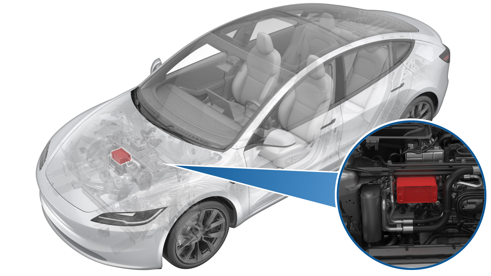
Service Kit - Liquid Cooled Condenser (Remove and Replace)
 Correction code
1840010062
FRT
1.02
NOTE: Unless otherwise explicitly stated in the procedure, the correction code and FRT listed above reflect all of the work required to perform this procedure, including the linked procedures. Do not stack correction codes unless explicitly told to do so.
NOTE: See Flat Rate Times to learn more about FRTs and how they are created.
NOTE: See Personal Protection to make sure you
are wearing proper PPE when performing the procedure below.
NOTE: See Ergonomic Precautions for safe and healthy working practices.
Correction code
1840010062
FRT
1.02
NOTE: Unless otherwise explicitly stated in the procedure, the correction code and FRT listed above reflect all of the work required to perform this procedure, including the linked procedures. Do not stack correction codes unless explicitly told to do so.
NOTE: See Flat Rate Times to learn more about FRTs and how they are created.
NOTE: See Personal Protection to make sure you
are wearing proper PPE when performing the procedure below.
NOTE: See Ergonomic Precautions for safe and healthy working practices.
- 2024-01-29: Added a step of vacuuming and refilling coolant.
Note
This procedure requires the A/C
Refrigerant (Recovery and Recharge) procedure to be performed. If not already
automatically added to the Service Visit, add correction code 18200102 as a
separate correction within the same activity to the Service Visit.
Torque Specifications
| Description | Torque Value | Recommended Tools | Reuse/Replace | Notes |
|---|---|---|---|---|
| Bolts (x4) that attach the liquid cooled condenser to the supermanifold |
 8 Nm (5.9 lbs-ft) |
|
Reuse |
Remove
- Raise and support the vehicle. See Raise Vehicle - 2 Post Lift.
- Recover the A/C refrigerant. See A/C Refrigerant (Recovery and Recharge) (Restore).
- Remove the LV battery. See LV Battery (Remove and Replace).
- Remove the front aero shield panel. See Panel - Aero Shield - Front (Remove and Replace).
- Remove the coolant bottle cap. See Cap - Coolant Reservoir (Remove and Replace).
-
Disconnect the powertrain bypass hose
from the Supermanifold.
NotePlug the hose and supermanifold as needed.
-
Disconnect the radiator outlet hose
from the Supermanifold.
NotePlug the hose and supermanifold as needed.
-
Disconnect the radiator inlet hose
from the Supermanifold
NotePlug the hose and supermanifold as needed.
-
Release the locking tab, and then
disconnect the electrical connector from the high pressure and temperature sensor.
CAUTIONDO NOT push down on the red locking tab. Pull the tab away from the connector until the connector is unlocked, and then continue pulling the main body of the connector to fully disconnect it.
-
Release the locking tab, and then
disconnect the electrical connector from the recirc EXV (expansion valve).
CAUTIONDO NOT push down on the red locking tab. Pull the tab away from the connector until the connector is unlocked, and then continue pulling the main body of the connector to fully disconnect it.
-
Release the locking tab, and then
disconnect the electrical connector from the liquid cooled condenser EXV.
CAUTIONDO NOT push down on the red locking tab. Pull the tab away from the connector until the connector is unlocked, and then continue pulling the main body of the connector to fully disconnect it.
-
Release the locking tab, and then
disconnect the electrical connector from the liquid cooled condenser shut off
valve.
CAUTIONDO NOT push down on the red locking tab. Pull the tab away from the connector until the connector is unlocked, and then continue pulling the main body of the connector to fully disconnect it.
-
Release the locking tab, and then
disconnect the electrical connector from the right side cabin condenser EXV.
CAUTIONDO NOT push down on the red locking tab. Pull the tab away from the connector until the connector is unlocked, and then continue pulling the main body of the connector to fully disconnect it.
-
Release the locking tab, and then
disconnect the electrical connector from the high pressure and temperature subcool
sensor.
CAUTIONDO NOT push down on the red locking tab. Pull the tab away from the connector until the connector is unlocked, and then continue pulling the main body of the connector to fully disconnect it.
-
Release the locking tab, and then
disconnect the electrical connector from the left side cabin condenser EXV.
CAUTIONDO NOT push down on the red locking tab. Pull the tab away from the connector until the connector is unlocked, and then continue pulling the main body of the connector to fully disconnect it.
-
Release the locking tab, and then
disconnect the electrical connector from the chiller EXV.
CAUTIONDO NOT push down on the red locking tab. Pull the tab away from the connector until the connector is unlocked, and then continue pulling the main body of the connector to fully disconnect it.
-
Release the locking tab, and then
disconnect the electrical connector from the evap EXV.
CAUTIONDO NOT push down on the red locking tab. Pull the tab away from the connector until the connector is unlocked, and then continue pulling the main body of the connector to fully disconnect it.
-
Move thermal harness from
supermanifold to side.
-
Remove the bolts (x4) that attach
liquid cooled condenser to Supermanifold.
TIpUse of the following tool(s) is recommended:
- 8 mm socket
- 6 in extension
- Flex head ratchet/flex head torque wrench
- Ratchet/torque wrench
WarningThe video(s) included in this procedure are meant as an overview for supplemental purposes only. Follow all of the steps listed in the procedure to avoid damage to components and/or personal injury. -
Slightly release top end of liquid
cooled condenser from supermanifold to allow any excess coolant to drain.
NoteLeave the AC ports of liquid cooled condenser intact to supermanifold to avoid any cross contamination.
-
Remove liquid cooled condenser from
Supermanifold.
-
Remove and discard the liquid cooled
condenser outlet and inlet gaskets from Supermanifold.
Install
-
Install new liquid cooled condenser
inlet and outlet gaskets to Supermanifold.
-
Install the liquid cooled condenser
onto Supermanifold.
NoteLubricate both O-rings on the liquid cooled condenser with the appropriate A/C oil. See Fluids and Capacities for A/C oil specifications. Then hand tighten the bolts that attach the cooled condenser to Supermanifold.NoteEnsure the liquid cooled condenser is fully seated on Supermanifold before installing the bolts.
-
Torque the bolts (x4) that attach the
liquid cooled condenser to Supermanifold in a cross-pattern.8 Nm (5.9 lbs-ft)WarningThe video(s) included in this procedure are meant as an overview for supplemental purposes only. Follow all of the steps listed in the procedure to avoid damage to components and/or personal injury.TIpUse of the following tool(s) is recommended:
- 8 mm socket
- 6 in extension
- Flex head ratchet/flex head torque wrench
- Ratchet/torque wrench
-
Route thermal harness back to
supermanifold.
-
Connect the electrical connector on
the evap EXV.
CAUTIONPush the red locking tab towards the connector to engage the locking mechanism. DO NOT push down or pull up on the red locking tab.
-
Connect the electrical connector on
the chiller EXV.
CAUTIONPush the red locking tab towards the connector to engage the locking mechanism. DO NOT push down or pull up on the red locking tab.
-
Connect the electrical connector on
the left side cabin condenser EXV.
CAUTIONPush the red locking tab towards the connector to engage the locking mechanism. DO NOT push down or pull up on the red locking tab.
-
Connect the electrical connector on
the right side cabin condenser EXV.
CAUTIONPush the red locking tab towards the connector to engage the locking mechanism. DO NOT push down or pull up on the red locking tab.
-
Connect the electrical connector on
the high pressure and temperature subcool sensor.
CAUTIONPush the red locking tab towards the connector to engage the locking mechanism. DO NOT push down or pull up on the red locking tab.
-
Connect the electrical connector on
the liquid cooled condenser shut off valve.
CAUTIONPush the red locking tab towards the connector to engage the locking mechanism. DO NOT push down or pull up on the red locking tab.
-
Connect the electrical connector on
the liquid cooled condenser EXV.
CAUTIONPush the red locking tab towards the connector to engage the locking mechanism. DO NOT push down or pull up on the red locking tab.
-
Connect the electrical connector on
the recirc EXV.
CAUTIONPush the red locking tab towards the connector to engage the locking mechanism. DO NOT push down or pull up on the red locking tab.
-
Connect the electrical connector on
the high pressure and temperature sensor.
CAUTIONPush the red locking tab towards the connector to engage the locking mechanism. DO NOT push down or pull up on the red locking tab.
-
Install the radiator inlet hose to
Supermanifold.
NoteRemove plugs from both ends of coolant connections before installation. Perform a push-pull-push test to make sure the hose is fully seated.
-
Install the radiator outlet hose to
Supermanifold.
NoteRemove plugs from both ends of coolant connections before installation. Perform a push-pull-push test to make sure the hose is fully seated.
-
Install the powertrain bypass hose to
Supermanifold.
NoteRemove plugs from both ends of coolant connections before installation. Perform a push-pull-push test to make sure the hose is fully seated.
- Remove the fluid catcher from underneath the vehicle.
- Install the front aero shield panel. See Panel - Aero Shield - Front (Remove and Replace).
- Vacuum and refill coolant. See Cooling System - Vacuum Refill (Test/Adjust).
- Perform the vacuum leak test and oil injection. See Vacuum Leak Test and Oil Injection.
-
Recharge the A/C refrigerant. See
A/C Refrigerant (Recovery and Recharge) (Restore).
CAUTIONRecharge the refrigerant exactly as instructed. Failure to adhere to the instructions can cause catastrophic damage to the cooling system.
- Connect the LV battery power. See LV Power (Disconnect and Connect).
- Unlock the vehicle gateway. See Gateway Unlock.
- On the touchscreen, touch , and allow the routine to complete.
-
On the touchscreen, touch , click Run, and then allow the routine to complete.
NoteMake sure the vehicle is not in Drive.NoteThe test will last for approximately 10 minutes. Monitor and keep the superbottle topped off while the test is running.
-
Inspect the coolant level and top off
as necessary.
NoteEnsure that the coolant is filled to the "Max" line.
- Install the coolant bottle cap.
- On the touchscreen, touch , click Run, and allow the routine to complete.
-
On the touchscreen, touch , click Run, and allow the routine to complete.
NoteTouch Close once the routine is passed.
-
On the touchscreen, touch , click Run, and allow the routine to complete.
NoteTouch Close once the routine is passed.
- Exit Service Mode through UI. See Service Mode.
- Install the underhood storage unit. See Underhood Storage Unit (Remove and Replace).
- Lower the lift arms fully and remove them from under the vehicle.