2025-10-22
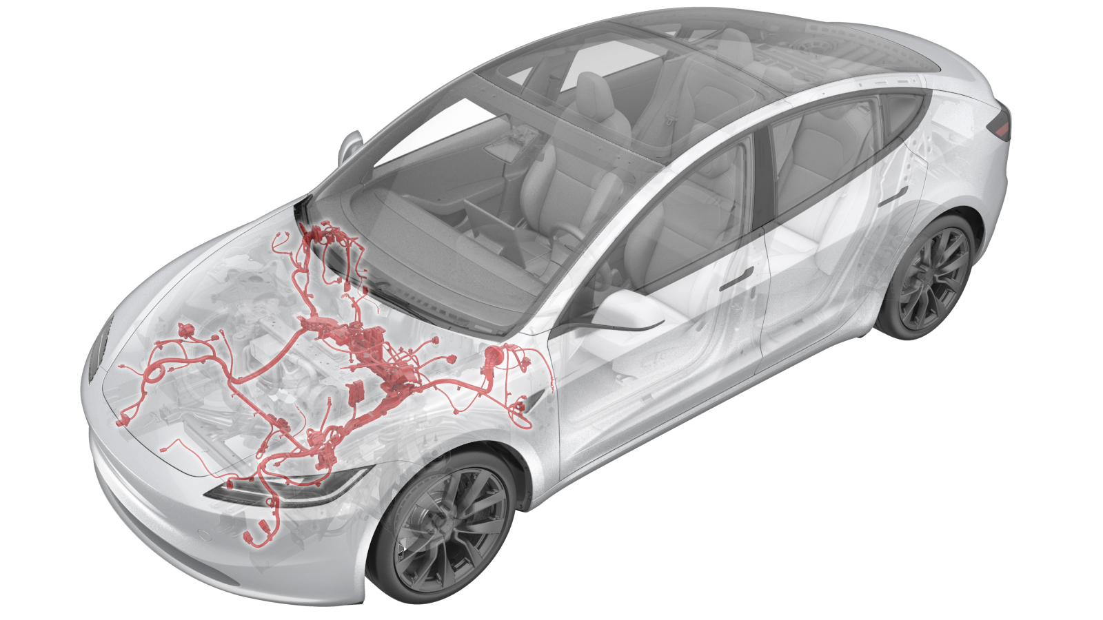
Harness - Main Front (Remove and Replace)
 Correction code
1710040022
4.32
NOTE: Unless otherwise explicitly stated in the procedure, the correction code and FRT listed above reflect all of the work required to perform this procedure, including the linked procedures. Do not stack correction codes unless explicitly told to do so.
NOTE: See Flat Rate Times to learn more about FRTs and how they are created.
NOTE: See Personal Protection to make sure you
are wearing proper PPE when performing the procedure below.
NOTE: See Ergonomic Precautions for safe and healthy working practices.
Correction code
1710040022
4.32
NOTE: Unless otherwise explicitly stated in the procedure, the correction code and FRT listed above reflect all of the work required to perform this procedure, including the linked procedures. Do not stack correction codes unless explicitly told to do so.
NOTE: See Flat Rate Times to learn more about FRTs and how they are created.
NOTE: See Personal Protection to make sure you
are wearing proper PPE when performing the procedure below.
NOTE: See Ergonomic Precautions for safe and healthy working practices.
- 2025-05-27: Added steps for removal and re-installation of the front body controller module.
- 2025-05-06: Added steps for removal and re-installation of the glove box.
- 2024-04-18: Updated the cover image.
Equipment:
- 1454796-00-A TOOLKIT, WINDOW SWITCH
Remove
- Remove the rear underhood apron. See Underhood Apron - Rear (Remove and Replace)
- Disconnect 12V/LV power. See LV Power (Disconnect and Connect).
- Remove the LH and RH lower A-pillar trim. See Trim - A-Pillar - Lower - LH (Remove and Replace).
- Remove the LH and RH knee airbag assembly, if equipped. See Airbag - Knee - LH (Remove and Replace).
- Remove the glove box. See Glove Box (Remove and Replace).
- Remove the wiper module. See Wiper Module (LHD) (Remove and Replace).
- Remove the front body controller module. See Module - Body Controller (Remove and Replace).
-
Remove bolt securing RH front harness
ground cable around RH A-pillar area
Note1x bolt, 10mm, 8 Nm,
-
Disconnect DCDC positive cable from
right body harness
Note1x connector, Pull up the red locking tab and then press
-
Release DCDC positive cable clip from
right body harness
Note1x clip
-
Disconnect connector from right body
harness
Note1x connector
-
Disconnect J1 connector from RH body
controller
Note1x connector, 1x locking tab, J1
-
Disconnect J6 connector from RH body
controller
Note1x connector, J6
-
Release harness clips from top of car
computer
Note2x clips
-
Disconnect the front fascia camera connector.
Note1x Connector, release locking tab, connector may not be present on early production vehicles
-
Disconnect RH front harness connector
on left side of car computer
Note1x connector
-
Disconnect RH front harness connectors
on right side of car computer
Note3x connectors, Release locking tabs
-
Release windshield heater connector
clips from the body
Note2x clips
-
Disconnect windshield heater
connector
Note1x connector
-
Release clips securing harness behind
RH shock tower
Note2x clips
-
Release grommet then remove RH front
harness from passenger side compartment
-
Disconnect LH front harness x121
connector from car computer
Note1x connector
-
Release LH front harness clips around
car computer left area
Note2x clips
-
Release LH front harness clips around
breaking pedal area
Note3x clips
-
Pull out LH front harness from right
to left
-
Disconnect LV power cable from left
body controller
Note1x connector, Release locking tab
-
Disconnect J6 frunk connector from LH
body controller
Note1x connector
-
Disconnect front harness white
connector X909 from LH body harness
Note1x connector
-
Release front harness from left body
controller
Note2x clips
-
Remove bolt securing LH front harness
ground cable around LH A-pillar area
Note1x bolt, 10mm, 8 Nm,
-
Release clips securing harness behind
LH shock tower
Note4x clips
-
Release grommet then remove LH front
harness from body
-
Disconnect brake fluid reservoir
connector
Note1x connector
-
Disconnect connector from brake
booster assembly
Note1x connector, Release locking tab
-
Disconnect harness connector from
brake booster assembly
Note1x connector, 1x connector, Depress locking tab and rotate to release
-
Disconnect hydraulic control unit
connector
Note1x connector, 1x connector, Depress locking tab and rotate to release
-
Disconnect HVIL connector
Note1x locking connector, Do not push down on red tab, Pull red tab to disengage lock, Pull tab again to release connector
-
Remove washer hose from LH front frame
rail area
Note1x clip
-
Release front harness clips around LH
front frame rail area
Note6x clips
-
Remove front harness ground terminal
at LH front shock tower
Note1x bolts, 10mm, 8 Nm, Inspect bolts: if they are self tapping tri-lobular bolts (1128269-00-A) then discard, If they are normal bolts (1447438-00-A) they can be reused
-
Remove LH front harness test
junction
Note1x bolt, 10mm, 8 Nm, Inspect bolt: if it is a self tapping tri-lobular bolt (1128269-00-A) then discard, If it is a normal bolt (1447438-00-A) it can be reused
-
Disconnect LH front acceleration
sensor connector
Note1x connector, Release locking tab
-
Release front harness clips from frunk
reinforcement bracket
Note3x clips
-
Remove AC compressor ground
strap
Note1x bolt, T25, 7 Nm
-
Disconnect steering gear assembly
connectors
Note4x connectors, Release locking tabs
-
Disconnect FDU front subframe
harness
Note1x connector, Release locking tab
-
Release clip securing radiator outlet
hose to LH side of vehicle
Note1x clip
-
Remove steering gear harness bracket
clip and remove from vehicle
Note2x clips
-
Disconnect LH front headlamp
Note1x connector, Pull tab to disengage lock mechanism, Pull again to release connector, Do not press down on tab, Connector style may vary
-
Disconnect washer pump connector
Note1x connector
-
Disconnect level sensor connector
Note1x connector
-
Release level sensor harness from
washer tank
Note4x clips
-
Remove AC Compressor harness clip from
front harness bracket
Note1x clip
-
Remove thermal sub-harness clip from
front harness bracket and moved to the side
Note1x clip
-
Release front harness clips around RH
front frame rail area
Note4x clips
-
Remove the front harness ground
terminal at RH front shock tower
Note1x bolts, 10mm, 8 Nm, Inspect bolts: if they are self tapping tri-lobular bolts (1128269-00-A) then discard, If they are normal bolts (1447438-00-A) they can be reused
-
Remove the front harness test junction
around RH front frame rail area
Note1x bolt, 10mm, 8 Nm, Inspect bolt: if it is a self tapping tri-lobular bolt (1128269-00-A) then discard, If it is a normal bolt (1447438-00-A) it can be reused
-
Disconnect RH front acceleration
sensor connector
Note1x connector, Release locking tab
-
Disconnect RH headlamp connector
Note1x locking connector, Do not push down on red tab, Pull red tab to disengage lock, Pull tab again to release connector
-
Remove and discard the nut
that attaches the DCDC positive cables to the RH body controller.
- Remove the wheel chocks.
-
With an assistant, move the
vehicle to a lift.
CAUTIONThe vehicle is safely pushed for only a very short distance and at a very slow speed.
- Remove the front LH and front RH wheels. See Wheel Assembly (Remove and Install).
- Remove the LH and RH front wheel arch liners. See Wheel Arch Liner - Front - LH (Remove and Replace).
-
Remove the front harness clip at the
rear of RH front wheel liner area for the side repeater and camera harness
Note1x clip
-
Disconnect the front harness
connectors for the RH side repeater and camera
Note2x connectors, Release locking tabs
-
Disconnect the RH front wheel speed
sensor
Note1x connector, Release locking tab
-
Release clip securing front harness to
front bumper fascia harness connector
Note1x clip
-
Disconnect front harness connector
from front fascia harness
Note1x connector, Release locking tab
-
Disconnect the front harness connector
for the RH front carrier harness
Note1x connector, Release locking tab
-
Remove the front harness clips from
the outer RH rail area
Note2x clips
-
Remove bolts securing front harness
bracket from vehicle
Note2x bolts,10mm,9 Nm
-
Remove LH harness bracket clip and
remove from vehicle
Note2x clips
-
Route the LH side of the front harness
from wheel liner to frunk area
-
Route the LH side of the front harness
toward the front controller area
-
Route the RH side of the front harness
from wheel liner to frunk area
-
Route the RH side of the front harness
toward the front controller area
-
Remove the front harness from
vehicle
Install
-
Position the front harness to vehicle
for installation
NoteMake sure to route RH branch underneath A/C compressor HV harness
-
Push LH front harness into driver side
compartment then secure grommet
-
Route LH front harness from frunk to
LH wheel liner area
-
Route LH front harness toward LH front
fascia area
NoteMake sure plastic housing is properly oriented with clips facing frame rail, Feed harness down behind fascia
-
Push RH front harness into passenger
side compartment then secure grommet
-
Route RH front harness from frunk to
RH wheel liner area
-
Route RH front harness toward RH front
fascia area
-
Secure LH harness bracket clips to
vehicle
Note2x clips
-
Install bolts securing front harness
bracket from vehicle
Note2x bolts,10mm,9 Nm
-
Secure clips securing harness behind
LH shock tower
Note4x clips
-
Connect brake fluid reservoir
connector
NoteConnect brake fluid reservoir connector
-
Connect connector to brake booster
assembly
Note1x connector, Secure locking tab
-
Connect harness connector from brake
booster assembly
Note1x connector, Secure locking tab
-
Connect hydraulic control unit
Note1x connector, Gently push connector downward, Secure locking tab
-
Secure front harness clips around LH
front frame rail area
Note6x clips
-
Secure washer hose to LH front frame
rail area
Note1x clip
-
Secure steering gear harness bracket
clips to vehicle
Note2x clips
-
Install clip securing radiator outlet
hose to RH side of vehicle
Note1x clip
-
Connect FDU front subframe
harness
Note1x connector, Secure locking tab
-
Connect steering gear assembly
Note4x connectors, Secure locking tabs
-
Install AC compressor ground
strap
Note1x bolt, T25, 7 Nm
-
Secure front harness clips to frunk
reinforcement bracket
Note3x clips
-
Connect HVIL connector
Note1x locking connector, 1x fir tree clip/1x adhesive clip, Engage locking tab, Clean BIW bracket area and secure harness adhesive clip when applicable on older VIN's, If BIW has a hole then no need to rework harness, Attach fir tree clip onto BIW bracket hole
-
Install bolts securing front harness
ground terminal at LH front shock tower
Note1x bolts, 10mm, 8 Nm,
-
Install bolt securing LH front harness
test junction
Note1x bolt, 10mm, 8 Nm,
-
Connect LH front acceleration sensor
connector
Note1x connector, Secure locking tab
-
Connect LH front headlamp
connector
Note1x connector, Secure locking tab
-
Secure level sensor harness to washer
tank
Note4x clips
-
Connect level sensor connector
Note1x connector
-
Connect washer pump connector
Note1x connector
-
Install the front harness clip around
RH front frame rail area
Note2x clips
-
Connect front harness connector for
the LH front carrier harness
Note1x connector, Secure locking tab
-
Connect front harness from cooling fan
module
Note1x connector
-
Connect LH front wheel speed
sensor
Note1x connector, Secure locking tab
-
Secure front harness clip for the LH
side repeater and camera harness
Note1x clip
-
Connect front harness connectors for
LH side repeater and camera
Note2x connectors, Secure locking tabs
- Install the RH front wheel arch liner. See Wheel Arch Liner - Front - LH (Remove and Replace).
- Install the front RH wheel. See Wheel Assembly (Remove and Install).
-
Secure harness clips behind RH shock
tower
Note2x clips
-
Connect windshield heater
Note1x connector
-
Secure windshield harness heater
connector clips to body
Note2x clips
-
Secure thermal sub-harness clip to
front harness bracket
Note1x clip
-
Secure AC Compressor harness clip to
front harness bracket
Note1x clip
-
Secure front harness clips around RH
front frame rail area
Note4x clips
-
Install bolt securing front harness
ground terminal at RH front shock tower
Note1x bolts, 10mm, 8 Nm
-
Install bolt securing front harness
test junction around RH front frame rail area
Note1x bolt, 10mm, 8 Nm,
-
Connect RH front acceleration sensor
connector
Note1x connector, Secure locking tab
-
Connect RH headlamp connector
Note1x connector, Secure locking tab
-
Secure front harness clips from the
outer RH rail area
Note2x clips
-
Connect front harness connector for
the RH front carrier harness
Note1x connector, Secure locking tab
-
Connect front harness connector from
front fascia harness
Note1x connector, Secure locking tabNoteOnly one connector may be present on early production vehicles.
-
Secure clip securing front harness to
front bumper fascia harness connector
Note1x clip
-
Connect RH front wheel speed
sensor
Note1x connector, Secure locking tab
-
Secure front harness clip at the rear
of RH front wheel liner area for the side repeater and camera harness
Note1x clip
-
Connect front harness connectors for
the RH side repeater and camera
Note2x connectors, Secure locking tabs
- Install the LH front wheel arch liner. See Wheel Arch Liner - Front - LH (Remove and Replace).
- Install the front LH wheel. See Wheel Assembly (Remove and Install).
-
With an assistant, remove
the vehicle from the lift.
CAUTIONThe vehicle is safely pushed for only a very short distance and at a very slow speed.
-
Secure front harness to left body
controller
Note2x clips
-
Connect front harness white connector
X909 to LH body harness
Note1x connector
-
Connect J6 frunk connector to LH body
controller
Note1x connector
-
Connect LV power cable to left body
controller
Note1x connector, Secure locking tab
-
Install bolt securing LH front harness
ground cable around LH A-pillar area
Note1x bolt, 10mm, 8 Nm,
-
Pull out LH front harness from left to
right
-
Secure LH front harness clips around
breaking pedal area
Note3x clips
-
Secure LH front harness clips around
car computer left area
Note2x clips
-
Connect LH front harness X121
connector from car computer
Note1x connector
-
Connect RH front harness connectors on
right side of car computer
Note3x connectors, Secure locking tabs
-
Install harness clips from top of car
computer
Note2x clips
-
Connect RH front harness connector on
left side of car computer
Note1x connector
-
Connect the front fascia camera connector.
Note1x Connector, release locking tab, connector may not be present on early production vehicles
-
Connect J6 connector to RH body
controller
Note1x connector, J6
-
Connect J1 connector to RH body
controller
Note1x connector, 1x locking tab
-
Connect connector to right body
harness
Note1x connector
-
Secure DCDC positive cable clip from
right body harness
Note1x clip
-
Connect DCDC positive cable from right
body harness
Note1x connector
-
Connect bolt securing RH front harness
ground cable around RH A-pillar area
Note1x bolt, 10mm, 8 Nm,
- Install the LH center console side panel carpet. See .Carpet - Front - LH (Remove and Replace)
- Install the LH and RH lower A-pillar trim. See Trim - A-Pillar - Lower - LH (Remove and Replace).
- Install the glove box. See Glove Box (Remove and Replace).
- Install the LH and RH knee airbag assembly, if equipped. See Airbag - Knee - LH (Remove and Replace).
- Install the front body controller module. See Module - Body Controller (Remove and Replace).
- Install the wiper module. See Wiper Module (LHD) (Remove and Replace).
- Install the underhood storage unit. See Underhood Storage Unit (Remove and Replace).
- Connect 12V/LV power. See LV Power (Disconnect and Connect).
- Install the rear underhood apron See Underhood Apron - Rear (Remove and Replace).
- Hold the brake pedal and select park on UI to disable EPB service mode.