2025-04-11
Halfshaft - Rear Drive Unit - LH (Remove and Replace)
 Correction code
4030010012
FRT
0.96
NOTE: Unless otherwise explicitly stated in the procedure, the correction code and FRT listed above reflect all of the work required to perform this procedure, including the linked procedures. Do not stack correction codes unless explicitly told to do so.
NOTE: See Flat Rate Times to learn more about FRTs and how they are created.
NOTE: See Personal Protection to make sure you
are wearing proper PPE when performing the procedure below.
NOTE: See Ergonomic Precautions for safe and healthy working practices.
Correction code
4030010012
FRT
0.96
NOTE: Unless otherwise explicitly stated in the procedure, the correction code and FRT listed above reflect all of the work required to perform this procedure, including the linked procedures. Do not stack correction codes unless explicitly told to do so.
NOTE: See Flat Rate Times to learn more about FRTs and how they are created.
NOTE: See Personal Protection to make sure you
are wearing proper PPE when performing the procedure below.
NOTE: See Ergonomic Precautions for safe and healthy working practices.
Equipment:
- 1498673-00-A KIT, CABLE AXLE REMOVER, MS/MX/M3
- 1096075-00-A Tool, Hub Puller, Hydraulic
- 1459409-00-A ADAPTER, HUB JACK, MODEL 3
Remove
- Raise and support the vehicle. See Raise Vehicle - 2 Post Lift.
- Open the LH front door and lower the LH front window.
- On the touchscreen, tap to place the vehicle into tow mode.
- Loosen the LH rear wheel lug nuts, but do not remove the wheel at this time. See Wheel Assembly (Remove and Install).
-
Loosen the LH rear halfshaft
nut.
- Remove the rear aero shield panel. See Panel - Aero Shield - Rear (Remove and Replace).
- Remove the LH rear wheel. See Wheel Assembly (Remove and Install).
-
Disconnect the LH rear EPB
caliper connector.
-
Remove and discard the bolts
(x2) that attach the LH rear caliper to the LH rear knuckle, remove the
caliper from the knuckle, and allow the caliper to hang from an
S-hook.
TIpUse of the following tool(s) is recommended:
- External Torx E18
- Ratchet/torque wrench
-
Remove and discard the nut,
and remove the washer that attach the LH halfshaft to the hub
assembly.
NoteThe washers are attached to the nut.TIpUse of the following tool(s) is recommended:
- Cordless Ratchet/Impact Driver
- 32 mm deep impact socket
-
Remove the bolt that
attaches the LH rear brake rotor to the hub.
NoteUse of the following tool(s) is recommended:
- Cordless Ratchet/Impact Driver
- 10 mm socket
- 2 in extension
-
Remove the LH rear rotor
from the vehicle.
NoteStore the rotor face down to reduce likelihood of damage to the rotor face.
-
Install the hub puller onto
the LH rear rotor, and then install and hand-tighten the puller washers (x5)
and the lug nuts (x5) onto the rotor studs.
- Use the hub puller to free the halfshaft from the hub splines.
- Remove the lug nuts (x5) and the puller washers (x5) from the LH rear rotor studs, and then remove the hub puller from the rotor.
-
Remove the bolt that attaches
the LH rear ABS wheel speed sensor to the knuckle.
TIpUse of the following tool(s) is recommended:
- 10 mm socket
- Flex head ratchet/flex head torque wrench
- 4 in extension
-
Remove the grommet that attaches
the LH rear ABS wheel speed sensor cable to the knuckle.
- Remove the LH rear suspension cover. See Cover - Rear Suspension - LH (Remove and Replace).
-
Install a spring compressor
onto the LH rear suspension spring:
WarningSprings in a compressed state are under large amounts of energy. Refer to the Tool Profile for the spring compressor kit prior to performing this step for additional warnings and cautions.
-
Remove and discard the nut
that attaches the LH stabilizer bar drop link to the LH rear suspension
knuckle.
TIpUse of the following tool(s) is recommended:
- 5 mm hex
- 15 mm combination flex head wrench
- 15 mm socket
- Flex head ratchet/flex head torque wrench
-
Remove the bolt and nut that
attach the LH rear upper aft link to the LH rear suspension knuckle.
TIpUse of the following tool(s) is recommended:
- 21 mm combination wrench
- 21 mm socket
- Flex head ratchet/flex head torque wrench
-
Remove the bolt and nut that
attach the LH rear upper fore link to the knuckle.
TIpUse of the following tool(s) is recommended:
- 18 mm combination wrench
- 18 mm socket
- Flex head ratchet/flex head torque wrench
-
Remove the bolt and nut that
attach the LH rear toe link to the LH rear suspension knuckle.
TIpUse of the following tool(s) is recommended:
- 18 mm socket
-
Remove the bolt and nut that
attach the LH rear lower fore link to the LH rear suspension knuckle.
NoteUse of the following tool(s) is recommended:
- 18 mm deep socket
- Lower the support stand to gain access for halfshaft removal.
-
With assistance, separate
the halfshaft from the hub assembly, and then move the halfshaft
aside.
WarningTo reduce the risk of personal injury, wear cut resistant gloves and proper personal protective equipment (PPE) as required when removing the halfshaft. Keep hands clear from other components to prevent injury when the halfshaft releases from the Drive Unit.
-
Position the axle remover cable around the inner joint of the LH rear drive
unit halfshaft, and then use a cable tie to hold the axle remover cable in
position.
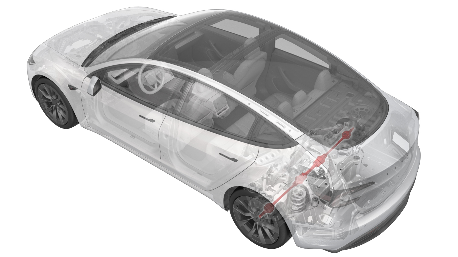
Figure 1. Axle removed from drive unit for demonstration purposes -
Hook the axle remover slide
hammer on the 2 axle remover cable loops, and then use the slide hammer to
remove the halfshaft from the drive unit.
WarningThe video(s) included in this procedure are meant as an overview for supplemental purposes only. Follow all of the steps listed in the procedure to avoid damage to components and/or personal injury.
Install
-
Apply Molykote
M-77 Lubricant Paste to the outboard side of the LH rear halfshaft
assembly.
NoteClean the halfshaft before applying if necessary.NoteApply no more than 1 gram to axle only.
-
Install the LH rear
halfshaft into the rear drive unit.
CAUTIONWhen installing the halfshaft to the drive unit:
- Take care not to damage or displace the oil seals.
- Carefully push the halfshaft into the drive unit until there is an audible "click" from the halfshaft stub contacting the pinion shaft.
- There will be a slight pulling sensation on the halfshaft as the halfshaft circlip locks into place.
- Pull on the inner halfshaft cup to confirm that the circlip is locked into place. If the halfshaft detaches from the drive unit then reinstall the halfshaft and then test that it is fully seated.
- With assistance, swing out the upper section of the knuckle and mate the LH rear halfshaft to the LH rear hub.
-
Position the LH rear lower
fore link onto the knuckle, and then install and hand-tighten the bolt and
nut.
-
Position the LH rear toe
link onto the knuckle, and then install and hand-tighten the bolt and
nut.
TIpRecommend assistance when performing this step.
-
Install the LH rear upper
fore link to the knuckle and hand-tighten the nut and bolt.
-
Position the LH rear upper
aft link onto the knuckle, and then install and hand-tighten the bolt and
nut.
-
Install and tighten a new
nut (1111542-00-A) that attaches the LH stabilizer bar drop link to the LH
rear suspension knuckle.
 55 Nm (40.6 lbs-ft)NoteCounter-hold the ball joint with a 5 mm hex wrench.NoteMark the nut with a paint pen after installation.TIpUse of the following tool(s) is recommended:
- 5 mm hex
- 15 mm combination flex head wrench
- 15 mm socket
- Flex head ratchet/flex head torque wrench
-
Install the grommet that
attaches the LH rear ABS wheel speed sensor cable to the knuckle.
-
Install the bolt that attaches
the LH rear ABS wheel speed sensor to the knuckle.5 Nm (3.7 lbs-ft)TIpUse of the following tool(s) is recommended:
- 10 mm socket
- Flex head ratchet/flex head torque wrench
- 4 in extension
-
Install the washer and a new
nut (1115558-00-A) that attach the LH halfshaft to the hub assembly.300 Nm (221.2 lbs-ft)NoteThe washers are attached to the nut.TIpUse of the following tool(s) is recommended:
- Cordless Ratchet/Impact Driver
- 32 mm deep impact socket
-
Install the hub jack adapter
onto the LH rear hub and hand-tighten the lug nuts (x5).
-
Position and raise the
underhoist stand to simulate the suspension at ride height.
-
Measure the distance between
the bottom of the quarter panel and the center of the rear axle to make sure
that the rear suspension is set to ride height. The distance should measure
378 mm.
-
Tighten the bolt and nut
that attach the LH rear upper aft link to the knuckle, and then mark the
bolt and nut with a paint pen.134 Nm (98.8 lbs-ft)TIpUse of the following tool(s) is recommended:
- 21 mm combination wrench
- 21 mm socket
- Flex head ratchet/flex head torque wrench
-
Tighten the bolt and nut
that attach the LH rear upper fore link to the knuckle, and then mark the
bolt and nut with a paint pen.76 Nm (56.0 lbs-ft)TIpUse of the following tool(s) is recommended:
- 18 mm combination wrench
- 18 mm socket
- Flex head ratchet/flex head torque wrench
-
Tighten the bolt and nut
that attach the LH rear toe link to the LH rear suspension knuckle. Mark the
bolt with a paint pen.76 Nm (56.0 lbs-ft)TIpUse of the following tool(s) is recommended:
- 18 mm socket
-
Tighten the bolt and nut
that attach the LH rear lower fore link to the LH rear suspension knuckle.
Mark the bolt with a paint pen.76 Nm (56.0 lbs-ft)NoteUse of the following tool(s) is recommended:
- 18 mm deep socket
-
Remove the underhoist stand
from underneath the LH rear suspension.
-
Remove the lug nuts (x5)
that attach the hub jack adapter, and then remove the hub jack adapter from
the vehicle.
-
Install the bolt that
attaches the LH rear brake rotor to the LH rear hub.5 Nm (3.7 lbs-ft)NoteUse of the following tool(s) is recommended:
- Cordless Ratchet/Impact Driver
- 10 mm socket
- 2 in extension
-
Install new bolts (x2)
(1088969-00-B) that attach the LH rear caliper to the LH rear knuckle.83 Nm (61.2 lbs-ft)TIpUse of the following tool(s) is recommended:
- External Torx E18
- Ratchet/torque wrench
WarningUpon installation, make sure that the flexible brake hose is not twisted and can bend forward. The flexible brake hose must not make contact with the wheel arch liner when the vehicle is lowered. -
Connect the LH rear EPB
caliper connector.
-
Remove the spring compressor
from the LH rear suspension spring:
WarningBe careful while unloading the spring. Hold the spring horizontally and facing away from you.WarningSprings in a compressed state are under large amounts of energy. Refer to the Tool Profile for the spring compressor kit prior to performing this step for additional warnings and cautions.
- Install the LH rear suspension cover. See Cover - Rear Suspension - LH (Remove and Replace).
- Install the rear aero shield panel. See Panel - Aero Shield - Rear (Remove and Replace).
- Install the LH rear wheel. See Wheel Assembly (Remove and Install).
-
Tighten the LH rear
halfshaft nut.300 Nm (221.2 lbs-ft)NoteUse of the following tool(s) is recommended:
- Long Breaker Bar
- 32 mm deep impact socket
- Exit the vehicle from "Towing" mode.
- Raise the LH front window and close the LH front door.
- Lower the vehicle. See Raise Vehicle - 2 Post Lift.