2025-07-10
Inverter Air Leak Test (Inspection)
 Correction code
40202020
0.66
NOTE: Unless otherwise explicitly stated in the procedure, the correction code and FRT listed above reflect all of the work required to perform this procedure, including the linked procedures. Do not stack correction codes unless explicitly told to do so.
NOTE: See Flat Rate Times to learn more about FRTs and how they are created.
NOTE: See Personal Protection to make sure you
are wearing proper PPE when performing the procedure below.
NOTE: See Ergonomic Precautions for safe and healthy working practices.
Correction code
40202020
0.66
NOTE: Unless otherwise explicitly stated in the procedure, the correction code and FRT listed above reflect all of the work required to perform this procedure, including the linked procedures. Do not stack correction codes unless explicitly told to do so.
NOTE: See Flat Rate Times to learn more about FRTs and how they are created.
NOTE: See Personal Protection to make sure you
are wearing proper PPE when performing the procedure below.
NOTE: See Ergonomic Precautions for safe and healthy working practices.
- 2024-07-25: Updated procedure to adapt to both 3DU and 4DU drive units.
- 1059330-00-B Skt, 1/4in Dr, 5-Lobe Torx Plus External
- 1450875-00-A Kit, Inverter Leak Test Adapter, M3
- 1140501-00-A Pack Kit, Enclosure, Leak Test, HV Battery, Complete
- 1140311-00-A Lever Lock, HV Connector, Model 3
- 1942298-00-A 4DU Inverter Leak Test Adapter
- 1880705-00-A 4DU Inverter Leak Test Plug Assembly
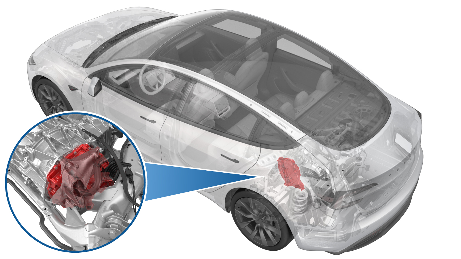
Note
Although the images in this procedure show the 3DU drive
unit, the procedure is the same for 4DU drive units.
Procedure
- Prepare the vehicle for lifting. See Raise Vehicle - 2 Post Lift.
- Perform the Vehicle HV Disablement Procedure. See Vehicle HV Disablement Procedure (Test/Adjust).
- Remove the rear aero shield panel. See Panel - Aero Shield - Rear (Remove and Replace).
-
Disconnect the rear drive
unit logic connector from the rear drive inverter.
-
Install the inverter leak test adapter into the rear drive unit logic
connector.
WarningThe video(s) included in this procedure are meant as an overview for supplemental purposes only. Follow all of the steps listed in the procedure to avoid damage to components and/or personal injury.
-
Slide to release the locking tab, and then rotate the release lever up to
disengage the connector that attaches the rear drive unit HV harness
connection to the rear drive inverter.
CAUTIONDo not force the release lever up.NoteMake sure that the alignment tabs on the rear drive unit header are not damaged.
-
Install the other leak test adapter
into the rear drive inverter header.
-
Connect the leak test
adapter to the enclosure leak test kit.
-
Turn the valve knobs to a vertical position to close both valves on the
enclosure leak test kit.
-
Connect the enclosure leak test kit to a compressed air supply line.
- Open the inlet valve, and set the regulator to 1 psi.
- Open the outlet valve to inject air into the rear drive inverter, and allow 60 seconds for the pressure to stabilize at 1 psi.
- Close the inlet valve and wait for 60 seconds for the pressure to settle.
- Record the starting pressure, then wait for 45 seconds, and then record the end pressure.
-
Subtract the ending pressure from the starting pressure, and if:
- The difference is greater than 0.2 psi, check the hose, adapter, and plug fittings, close the outlet valve and open the inlet valve, check the enclosure leak test kit pressure, and then retest from step 9. If the difference is still greater than 0.2 psi, further investigate possible causes for the pressure leak If the cause for the pressure leak can still not be found and resolved, escalate a Toolbox session.
- The difference is 0.2 psi or less, continue the procedure.
-
Disconnect the compressed air supply line from the enclosure leak test
kit.
-
Disconnect the leak test adapter to the enclosure leak test kit.
-
Remove the leak test adapter from the rear drive inverter.
-
Install the HV connector lever lock to the rear drive unit HV cable
connector.
-
Align the connector to the
rear drive unit, and then remove the HV connector lever lock before fully
latching the connector.
-
Latch the locking tab to connect the rear drive unit HV harness to the rear
drive unit.
NoteOnce connected, verify that the locking tab is not damaged and the rear drive unit HV connector is fully secured in the latched position.
-
Remove the inverter leak
test adapter from the rear drive unit logic connector.
-
Secure the rear drive unit logic connector to the rear drive
inverter.
CAUTIONMake sure that there is no coolant ingress in the connector.
- Install the rear aero shield panel. See Panel - Aero Shield - Rear (Remove and Replace).
- Install the 2nd row seat cushion. See Seat Cushion - 2nd Row (Remove and Replace).
- Connect the LV battery power. See LV Power (Disconnect and Connect).