Damper - Front - LH (Dual Motor) (Performance) (Remove and Replace)
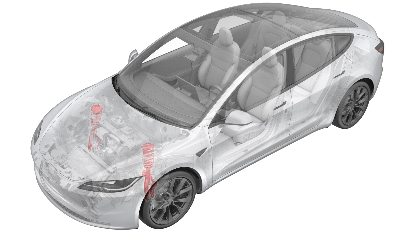 Correction code
3115010302
FRT
0.48
NOTE: Unless
otherwise explicitly stated in the procedure, the correction code and its
associated FRT reflect all of the work required to perform this procedure,
including the linked procedures. Do not stack correction
codes unless explicitly told to do so.
NOTE: See Flat Rate Times to
learn more about FRTs and how they are created.
NOTE: See Personal Protection to make
sure you are wearing proper PPE when performing the procedure below.
NOTE: See Ergonomic Precautions for safe and healthy
working practices.
Correction code
3115010302
FRT
0.48
NOTE: Unless
otherwise explicitly stated in the procedure, the correction code and its
associated FRT reflect all of the work required to perform this procedure,
including the linked procedures. Do not stack correction
codes unless explicitly told to do so.
NOTE: See Flat Rate Times to
learn more about FRTs and how they are created.
NOTE: See Personal Protection to make
sure you are wearing proper PPE when performing the procedure below.
NOTE: See Ergonomic Precautions for safe and healthy
working practices.
- 2026-08-18: Released new procedure.
Equipment:
- 1467109-00-A Strut Removal Socket, 13mm, M3
Torque Specifications
| Description | Torque Value | Recommended Tools | Reuse/Replace | Notes |
|---|---|---|---|---|
| Nuts (x3) that attach the LH front damper assembly to the LH front upper control arm mount |
 23 Nm (17.0 lbs-ft) |
|
Reuse | |
| Bolt that attaches the LH front ABS wheel speed sensor to the knuckle |
5 Nm (3.7 lbs-ft) |
|
Reuse | |
| Nut that attaches the front stabilizer bar end link to the LH front strut |
98 Nm (72.3 lbs-ft) |
|
Replace | 1111543-00-A |
| Bolt and nut that attach the LH front upper control arm to the knuckle |
56 Nm (41.3 lbs-ft) |
|
Nut: Replace Bolt: Reuse |
|
| Bolt and nut that attach the strut to the lower control arm |
106 Nm (78.2 lbs-ft) |
|
Reuse |
Remove
- Inspect the vehicle for abnormal tire wear that might indicate the need for a wheel alignment. Note any findings.
- Remove the rear underhood apron. See Underhood Apron - Rear (Remove and Replace).
- Remove the cabin intake duct. See Assembly - Fresh Air Gutter - HVAC (Remove and Replace).
- Remove the access panel. See Cover - Hood Latch (Remove and Replace).
- Remove the underhood storage unit. See Underhood Storage Unit (Remove and Replace).
-
Remove the nuts (x3) that attach the
LH front damper assembly to the LH front upper control arm mount.
TipUse of the following tool(s) is recommended:
- Strut Removal Socket, 13mm, M3
NoteStandard sockets will not fit the upper fastener mounting holes. - Remove the LH front wheel. See Wheel Assembly (Remove and Install).
-
Release the clips (x2) that
attach the LH front wheel speed sensor harness to the LH front upper control
arm, and then set the harness aside.
-
Remove and discard the nut that
attaches the front stabilizer bar end link to the LH front strut and separate
the end link from the strut.
NoteCounter-hold the ball joint while loosening the nut.TipIf needed, use a pry bar to release the end link.TipUse of the following tool(s) is recommended:
- 18 mm combination wrench
- Torx T40 socket
- Cordless Ratchet/Impact Driver
- Ratchet/torque wrench
-
Remove the bolt and nut that
attach the LH front upper control arm to the knuckle, and then discard the
nut.
NoteCompress the upper control arm ball joint downwards to help release the bolt.TipUse of the following tool(s) is recommended:
- 15 mm combination wrench
- Torx T50 socket
- Cordless Ratchet/Impact Driver
- Flex head ratchet/flex head torque wrench
-
Remove the bolt and nut that
attach the strut to the lower control arm.
NoteNote the direction of the bolt and nut before removal.NoteUse of the following tool(s) is recommended:
- 21 mm combination wrench
- 21 mm socket
- Flex head ratchet/flex head torque wrench
-
Remove the coil spring and damper
assembly from the LH front upper control arm mount.
WarningThe video(s) included in this procedure are meant as an overview for supplemental purposes only. Follow all of the steps listed in the procedure to avoid damage to components and/or personal injury.
-
Remove the coil spring and damper
assembly from the vehicle.
TipLift the upper control arm to create clearance for removal.
Replace
-
Maneuver the coil spring and damper
assembly into place.
TipLift the upper control arm to create clearance for installation.
-
Install the coil spring and damper
assembly to the LH front upper control arm mount.
-
Hand tighten the bolt and nut
that attach the strut to the lower control arm.
-
Install the nuts (x3) that attach the
LH front damper assembly to the LH front upper control arm mount.23 Nm (17.0 lbs-ft)TipUse of the following tool(s) is recommended:
- Strut Removal Socket, 13mm, M3
-
Position the front stabilizer
end link onto the LH front strut, and then install a new nut that attaches the
front stabilizer end link to the LH front strut.98 Nm (72.3 lbs-ft)NoteCounter-hold the ball joint while torquing the nut.TipIf needed, use a pry bar to help position the end link.TipUse of the following tool(s) is recommended:
- 18 mm combination wrench
- Torx T40 socket
- Cordless Ratchet/Impact Driver
- Ratchet/torque wrench
-
Position the LH front control
arm to the knuckle, and then install the nut and a new bolt that attach the LH
front upper control arm to the knuckle.56 Nm (41.3 lbs-ft)TipUse of the following tool(s) is recommended:
- 15 mm combination wrench
- Torx T50 socket
- Cordless Ratchet/Impact Driver
- Flex head ratchet/flex head torque wrench
-
Install the clips (x2) that
attach the LH front wheel speed sensor harness to the LH front upper control
arm.
-
Install the bolt that attaches
the LH front ABS wheel speed sensor to the knuckle.5 Nm (3.7 lbs-ft)TipUse of the following tool(s) is recommended:
- 10 mm deep socket
-
Remove the bolt that attaches
the LH front rotor to the LH front hub.
NoteUse of the following tool(s) is recommended:
- Cordless Ratchet/Impact Driver
- 10 mm socket
- 2 in extension
-
Install the hub jack adapter
onto the LH front hub and hand-tighten the lug nuts (x5).
-
Position and raise the
underhoist stand to simulate the suspension at ride height.
-
Measure the distance between the
bottom of the fender and the center of the front axle to make sure that the
front suspension is set to ride height. The distance should measure 423
mm.
-
Tighten the bolt and nut that
attach the strut to the lower control arm.106 Nm (78.2 lbs-ft)TipUse of the following tool(s) is recommended:
- 21 mm combination wrench
- 21 mm socket
- Flex head ratchet/flex head torque wrench
-
Remove the underhoist stand from
underneath the LH front suspension.
-
Remove the lug nuts (x5) that
attach the hub jack adapter, and then remove the hub jack adapter from the
vehicle.
NoteGently tap with a dead blow to aid
-
Install the bolt that attaches
the LH front rotor to the LH front hub.5 Nm (3.7 lbs-ft)NoteUse of the following tool(s) is recommended:
- Cordless Ratchet/Impact Driver
- 10 mm socket
- 2 in extension
- Install the LH front wheel. See Wheel Assembly (Remove and Install).
- Install the underhood storage unit. See Underhood Storage Unit (Remove and Replace).
- Install the access panel. See Cover - Hood Latch (Remove and Replace).
- Install the cabin intake duct. See Assembly - Fresh Air Gutter - HVAC (Remove and Replace).
- Install the rear underhood apron. See Underhood Apron - Rear (Remove and Replace).
- Refer to the Alignment Requirement tables to determine whether an EPAS alignment check (EC) or four wheel alignment check (AC) is necessary. If performed, add the alignment check/adjust as a separate activity. See Alignment Requirement - Suspension.