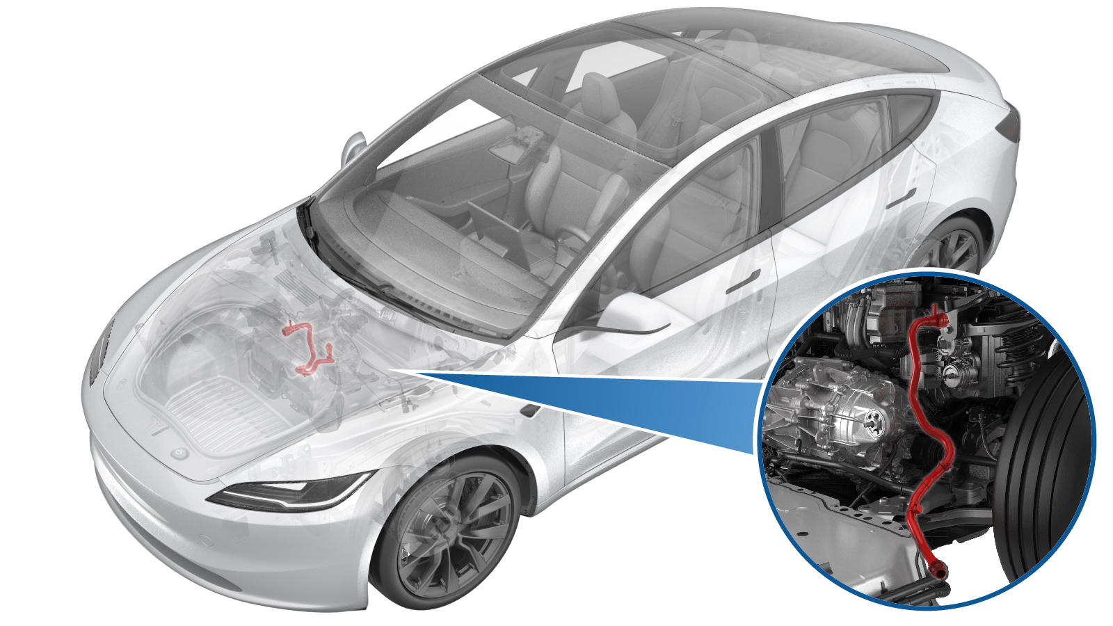
Hose - Powertrain Supply (Remove and Replace)
 Correction code
1830020112
FRT
0.72
NOTE: Unless otherwise explicitly stated in the procedure, the correction code and FRT listed above reflect all of the work required to perform this procedure, including the linked procedures. Do not stack correction codes unless explicitly told to do so.
NOTE: See Flat Rate Times to learn more about FRTs and how they are created.
NOTE: See Personal Protection to make sure you
are wearing proper PPE when performing the procedure below.
NOTE: See Ergonomic Precautions for safe and healthy working practices.
Correction code
1830020112
FRT
0.72
NOTE: Unless otherwise explicitly stated in the procedure, the correction code and FRT listed above reflect all of the work required to perform this procedure, including the linked procedures. Do not stack correction codes unless explicitly told to do so.
NOTE: See Flat Rate Times to learn more about FRTs and how they are created.
NOTE: See Personal Protection to make sure you
are wearing proper PPE when performing the procedure below.
NOTE: See Ergonomic Precautions for safe and healthy working practices.
Equipment:
- 1080568-00-A Fluid Catcher
- 1135762-00-A Kit, Svc Plug, Cooling Hose, Model 3
- 1065131-00-A Kit, Battery Coolant Drain
| Description | Torque Value | Recommended Tools | Reuse/Replace | Notes |
|---|---|---|---|---|
| Bolt that secures the RH front wheel liner to the skid plate |
 5 Nm (3.7 lbs-ft) |
|
Reuse |
Remove
- Raise and support the vehicle. See Raise Vehicle - 2 Post Lift.
- Disconnect the LV battery power. See LV Power (Disconnect and Connect).
- Remove the underhood storage unit. See Underhood Storage Unit (Remove and Replace).
-
Raise the vehicle fully and lower the lift onto locks.
CAUTION
Make sure there is an audible click of the locks on both sides before lowering, otherwise the vehicle may tilt to one side.
Make sure that the doors are clear of surrounding objects.
- Remove the front aero shield panel. See Panel - Aero Shield - Front (Remove and Replace).
-
Remove the bolt that secures the RH
front wheel liner to the skid plate.
TIpUse of the following tool(s) is recommended:
- Cordless 1/4in Dr Ratchet
- Nutsetter 1/4in Dr. 6in. X 10mm Magnetic Deep
- 10 mm deep socket
- Ratchet/torque wrench
-
Remove the push clips (x3) that secure the lower rear edge of the RH front wheel
liner to the vehicle for access to the coolant hose.
- Use a bungee strap to pull back the RH front wheel liner and secure it to the subframe.
- Position the coolant drain container underneath the RH front of the HV battery.
-
Release the spring clip and the plugs (x2) to disconnect the powertrain supply hose
from the powertrain supply tube, and then plug the ends of both fittings as soon as
possible to avoid coolant loss.
NoteCoolant loss greater than 1L requires vacuum fill.
-
Release the powertrain supply hose clips (x2) from the vehicle.
- Remove the coolant drain container from underneath the vehicle.
- Lower the vehicle to a comfortable working height and set the lift onto locks.
- Position the fluid catcher underneath the front of the vehicle.
- Remove the fresh intake duct. See Fresh Air Intake - HVAC (Remove and Replace).
- Pull the red locking tab to disengage the lock, and then hold and pull it again to release the electrical connector, so that the powertrain supply hose sensor is disconnected.
-
Release the spring clip and the plugs (x2) to disconnect the powertrain supply hose
from the supermanifold, and then plug the ends of both fittings as soon as possible to
avoid coolant loss.
NoteCoolant loss greater than 1L requires vacuum fill.
-
Remove the powertrain supply hose from the vehicle.
Install
- Install the powertrain supply hose to the vehicle and place a coolant plug on the lower end of the hose to avoid coolant loss.
-
Remove the plugs on the ends of fittings as quickly as possible to avoid coolant
loss, and then secure the spring clip and the plug to connect the powertrain supply hose
to the supermanifold.
NotePerform a push-pull-push test to make sure that the hose is fully secured.
-
Engage the locking tab to connect the powertrain supply hose sensor.
NoteThe harness and the coolant hose are color coded. Match the color of the harness to the color of the coolant hose.
- Install the fresh intake duct. See Fresh Air Intake - HVAC (Remove and Replace).
- Remove the fluid catcher from underneath the vehicle.
-
Raise the vehicle fully and lower the lift onto locks.
CAUTION
Make sure there is an audible click of the locks on both sides before lowering, otherwise the vehicle may tilt to one side.
Make sure that the doors are clear of surrounding objects.
- Position the coolant drain container underneath the RH front of the HV battery.
-
Remove the plugs on the ends of fittings as quickly as possible to avoid coolant
loss, and then secure the spring clip and the plugs (x2) to connect the powertrain
supply hose to the powertrain supply tube.
Note
Perform a push-pull-push test to make sure that the hose is fully secured.
Coolant loss greater than 1L requires vacuum fill.
-
Secure the powertrain supply hose clips (x2) to the vehicle.
- Remove the coolant drain container from underneath the vehicle.
- Release the RH front wheel liner from the bungee strap, and remove the strap from the vehicle.
-
Install the push clips (x3) that secure the lower rear edge of the RH front wheel
liner to the vehicle.
-
Install the bolt that secures the RH front wheel liner to the skid plate.5 Nm (3.7 lbs-ft)TIpUse of the following tool(s) is recommended:
- Cordless 1/4in Dr Ratchet
- Nutsetter 1/4in Dr. 6in. X 10mm Magnetic Deep
- 10 mm deep socket
- Ratchet/torque wrench
- Install the front aero shield panel. See Panel - Aero Shield - Front (Remove and Replace).
- Lower the vehicle fully.
- Connect the LV battery power. See LV Power (Disconnect and Connect).
- Remove the coolant bottle cap and fill the coolant to the "MAX" line.
- Unlock the vehicle gateway. See Gateway Unlock.
-
On the touchscreen, tap the Service
Mode "wrench" (at the bottom of the touchscreen UI), and then tap to start the coolant air purge.
Note
- The routine will last for a while after the stop message displays. The coolant pumps are audible.
- The test lasts for approximately 10 mins. Do not start another routine during this time.
- Make sure that the vehicle is not in Drive. Putting the vehicle into Drive will stop this routine.
- The speed in the test varies from 3500-6500 RPM (idle speed = ~1500 RPM) and the actuated valve varies between SERIES and PARALLEL.
- If the speed hovers at 7000 RPM, it indicates the pumps are air locked. Perform the vacuum fill again. Continue to add the coolant and purge until the coolant level reaches between the NOM and MAX Lines on the bottle.
-
Inspect the coolant level, top off as
necessary, and then install the coolant bottle cap.
NoteEnsure that the coolant level is at the "Max" line.
- Install the underhood storage unit. See Underhood Storage Unit (Remove and Replace).
- Raise the LH front window and close the LH front door.
- Remove the lift arms from below the vehicle.