2025-04-11
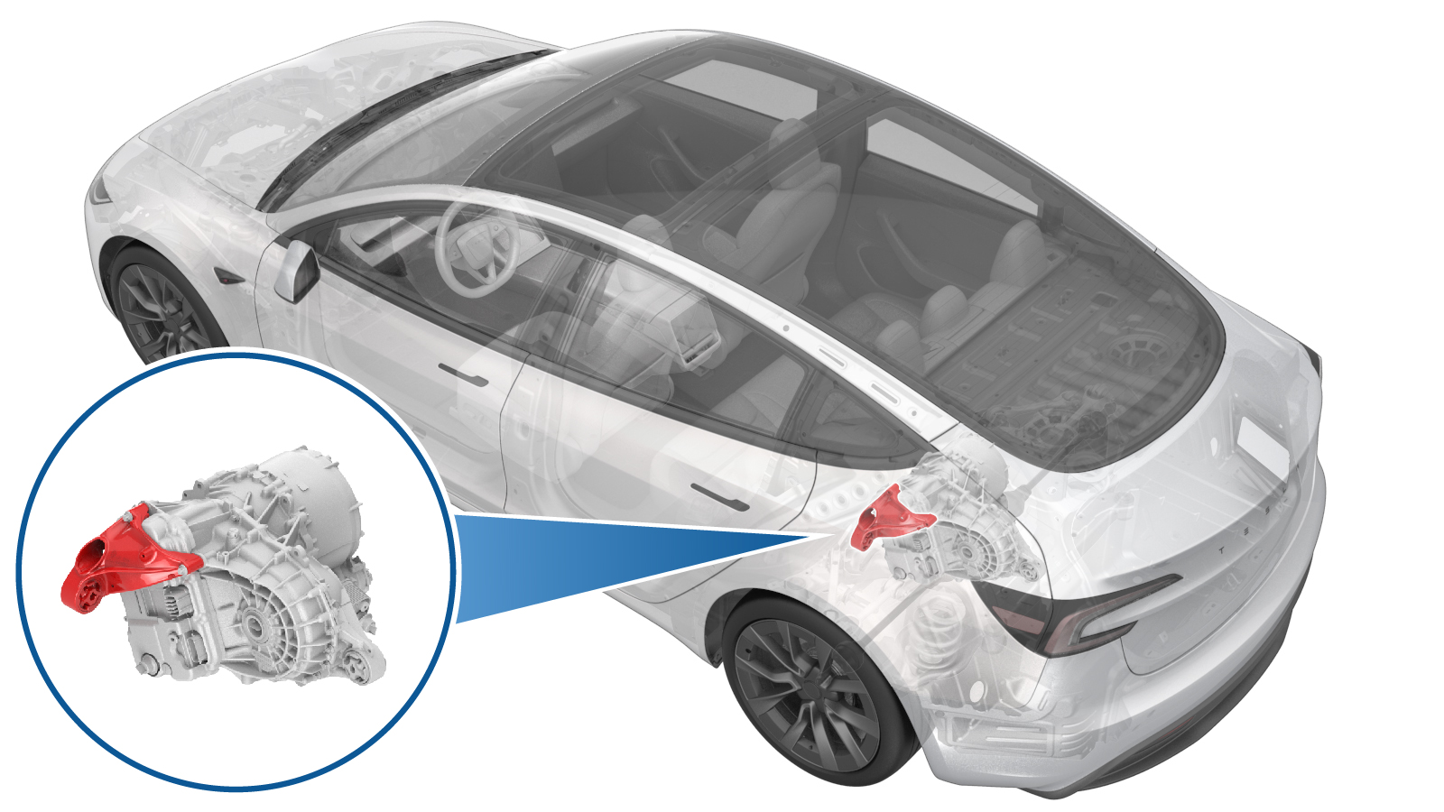
Mount - Rear Drive Unit - LH (4DU) (Remove and Replace)
 Correction code
4001010092
FRT
2.16
NOTE: Unless otherwise explicitly stated in the procedure, the correction code and FRT listed above reflect all of the work required to perform this procedure, including the linked procedures. Do not stack correction codes unless explicitly told to do so.
NOTE: See Flat Rate Times to learn more about FRTs and how they are created.
NOTE: See Personal Protection to make sure you
are wearing proper PPE when performing the procedure below.
NOTE: See Ergonomic Precautions for safe and healthy working practices.
Correction code
4001010092
FRT
2.16
NOTE: Unless otherwise explicitly stated in the procedure, the correction code and FRT listed above reflect all of the work required to perform this procedure, including the linked procedures. Do not stack correction codes unless explicitly told to do so.
NOTE: See Flat Rate Times to learn more about FRTs and how they are created.
NOTE: See Personal Protection to make sure you
are wearing proper PPE when performing the procedure below.
NOTE: See Ergonomic Precautions for safe and healthy working practices.
Remove
- Inspect the vehicle for abnormal tire wear that might indicate the need for a wheel alignment. Note any findings.
- Raise and support the vehicle. See Raise Vehicle - 2 Post Lift.
- Open all doors and lower all windows.
- Enter Service Mode. See Service Mode.
- Unlock the vehicle gateway. See Gateway Unlock.
-
Tap , tap
Run
, and allow the routine to complete. -
On the touchscreen, tap the Service
Mode "wrench" (at the bottom of the touchscreen UI), and then tap , tap
Run
, and allow the routine to complete. - Remove the rear underhood apron. See Underhood Apron - Rear (Remove and Replace).
- Disconnect LV power. See LV Power (Disconnect and Connect).
- Remove the fresh air gutter. See Assembly - Fresh Air Gutter - HVAC (Remove and Replace).
- Remove the 2nd row lower seat cushion, See Seat Cushion - 2nd Row (Remove and Replace).
- Perform the Vehicle HV Disablement Procedure. See Vehicle HV Disablement Procedure (Test/Adjust).
- Remove the rear wheels. See Wheel Assembly (Remove and Install).
- Remove the rear aero shield panel, See Panel - Aero Shield - Rear (Remove and Replace).
- Remove the LH and RH rear suspension covers. See Cover - Rear Suspension - LH (Remove and Replace).
- Remove the rear fascia assembly. See Fascia Assembly - Rear (Remove and Install).
-
Remove the nut that attaches the rear
drive unit ground strap to the body.
TIpUse of the following tool(s) is recommended:
- 10 mm 12-point deep socket
- Ratchet/torque wrench
-
Disconnect the RH subframe harness
electrical connector.
-
Remove the RH side subframe harness
clips (x2) from body.
-
Remove and discard the nuts (x2) that
attach the stabilizer bar to the end links, and then remove the stabilizer bar from the
end links.
NoteLoosen the nut first, and then continue to remove the nut by counter-holding the ball joint with a hex wrench.NoteMight need to move the rear stabilizer bar up/down to get the correct angle in order to remove the end links.TIpUse of the following tool(s) is recommended:
- 15 mm socket
- Flex head ratchet/flex head torque wrench
-
Release clips (x4) that secure the
coolant hoses to LH and RH shear plates.
Figure 1. LH Shown, RH Similar - Remove the HV battery rear skid plate enclosure. See Skid Plate - HV Battery - Rear (Remove and Replace).
- Remove the rear drive unit inverter inlet hose. See Hose - Inlet - Rear Drive Unit Inverter (Remove and Replace).
-
Release the rear drive unit logic
connection.
NoteDo not get coolant ingress into this connector. Move the connector aside as needed.
-
Release the rear drive unit logic
connection clip.
- Remove the rear drive unit HV harness assembly. See HV Harness - HV Battery to Rear Drive Unit (Remove and Replace).
- Remove coolant drain container from underneath vehicle.
-
Place the subframe lifting tool into
position underneath the rear subframe.
-
Connect the air supply to the subframe
lifting tool.
-
Raise the subframe lifting tool to
support the rear subframe, and then with the help of an assistant, fully secure the
straps (x3) that attach the rear subframe to the subframe lifting tool.
Note3x straps, Attach metal hooks at the end of straps to rings on subframe lifting tool and pull straps until secure, Lower the vehicle if necessary, Recommend assistance.
-
Use a paint pen to trace around the LH
and RH rear subframe mounting bolts, so that the bolts can be realigned later during the
subframe installation.
-
Use a paint pen to apply a witness
mark where the rear subframe contacts the body at the LH and RH rear subframe mounting
bolts, so that the subframe can be realigned to the body later during subframe
installation.
- Remove the LH and RH shear plates. See Shear Plate - Rear Subframe - LH (Remove and Replace).
-
Remove and discard the LH rear
subframe bolt that attaches the subframe to the body.
TIpUse of the following tool(s) is recommended:
- 21 mm socket
-
Remove and discard the LH rear subframe bolt that attaches the subframe to the
body.
TIpUse of the following tool(s) is recommended:
- 21 mm socket
-
Partially lower the rear subframe and
drive unit assembly.
NoteLower the subframe partially, Use caution while lowering subframe as multiple components are still attached, Do not overstrain these components, The dampers and brake calipers are still connected, Recommend lowering about 3.25in or 8.25cm.
-
Tilt the subframe fixture
forward.
NoteAdjust the powertrain lift and tilt it forward in order to access motor mount fasteners.
-
Support center of the RDU with
protective block.
NoteUsing a rubber or wood block to support. Do not damage the drive unit.
-
Release rear drive unit ground strap
clip from the subframe.
-
Release the clip that attach the
inverter to the cooler hose.
-
Release the clips (x2) that attach
rear drive unit inverter to the oil cooler hose.
-
Remove the LH mount bolt that attach
the rear drive unit LH mount to the subframe.
NoteUse a pry bar between the block and rear drive unit to unload the bolt so that it can be removed.TIpUse of the following tool(s) is recommended:
- 18 mm socket
- Ratchet/torque wrench
-
Remove and discard the bolts (x3) that
attach the rear drive unit LH mount to the rear drive unit.
NoteUse of the following tool(s) is recommended:
- External Torx Plus EP14
-
Release the clip, disconnect the rear
drive unit inverter to heat exchanger hose from the rear drive unit inverter outlet, and
then immediately plug both fitting.
-
Remove the rear drive unit LH mount
up, over, and out between the rear subframe and the body.
Install
-
Install the rear drive unit LH mount
in, over, and down between the rear subframe and the body.
-
Remove the plugs from the fittings,
immediately connect the rear drive unit inverter to heat exchanger hose to the rear
drive unit inverter outlet, fasten the clip, and then perform a Push-Pull-Push check of
the fitting.
-
Install the rear drive unit LH mount
to the rear drive unit, and then install and hand-tighten new bolts (x3) to attach the
mount to the drive unit.
NoteFollow the sequence shown in image to hand-tighten the bolts.
-
Tighten the bolts (x3) that attach the
rear drive unit LH mount to the rear drive unit in the sequence shown.
 35 Nm (25.8 lbs-ft) +55 degNoteUse of the following tool(s) is recommended:
- External Torx Plus EP14
-
Install the LH mount bolt that
attaches the rear drive unit LH mount to the rear subframe.80 Nm (59.0 lbs-ft)NoteUse a pry bar between the block and rear drive unit to position the mount so that the bolt can be installed.TIpUse of the following tool(s) is recommended:
- 18 mm socket
- Ratchet/torque wrench
-
Fasten the clips (x2) that attach the
rear drive unit inverter to heat exchanger hose to the rear drive unit.
-
Fasten the clip that attaches the rear
drive unit inverter to the coolant hose.
-
Fasten the clip that attaches the rear drive unit ground strap to the rear
subframe.
-
Remove the block from between the rear
drive unit and the subframe fixture.
-
Tilt the subframe fixture backward to
its original position.
-
Carefully raise the subframe and rear
drive unit assembly until they are up against the body.
CAUTIONBe mindful of the suspension and brake components that are still attached to both the subframe and the body.
-
Install and hand-tighten a new RH rear
subframe bolt to attach the rear subframe to the body.
-
Install and hand-tighten a new LH rear
subframe bolt to attach the rear subframe to the body.
-
Install the LH and RH shear plates. See Shear Plate - Rear Subframe - LH (Remove and Replace).
NoteNo not tighten the bolts (x6) that attch the LH and RH shear plate to the body yet.
-
Use a pry bar to shimmy the rear
subframe with respect to the body, so that the subframe mounting bolts are centered in
the tracings, and the witness marks align where the subframe contacts the body.
-
Tighten the RH rear subframe bolt that
attaches the rear subframe to the body, and then mark the bolt after tightenting.165 Nm (121.7 lbs-ft)TIpUse of the following tool(s) is recommended:
- 21 mm socket
-
Tighten the LH rear subframe bolt that
attaches the rear subframe to the body, and then mark the bolt after tightenting.165 Nm (121.7 lbs-ft)TIpUse of the following tool(s) is recommended:
- 21 mm socket
- Tighten the bolts (x6) that attach the LH and RH shear plates to the body. See Shear Plate - Rear Subframe - LH (Remove and Replace).
-
Release the straps (x3) that attach
the rear subframe to the subframe lifting tool.
-
Disconnect the air supply from the subframe lifting tool.
-
Lower the subframe lifting tool, and
move it out from under the vehicle.
- Install the rear drive unit HV harness assembly. See HV Harness - HV Battery to Rear Drive Unit (Remove and Replace).
-
Verify there is no coolant ingress in
the rear drive unit logic connector, and then secure the connector.
-
Secure the rear drive unit logic
connection clip.
- Position the coolant drain container underneath the LH rear of HV battery.
- Install the rear drive unit inverter inlet hose. See Hose - Inlet - Rear Drive Unit Inverter (Remove and Replace).
- Install the high voltage skid plate. See Skid Plate - HV Battery - Rear (Remove and Replace).
-
Install the clips (x4) that attach the
coolant hoses to the LH and RH shear plates.
-
Align the LH and RH end links with the
rear stabilizer bar.
NoteMove the rear stabilizer bar up/down to get the correct angle to install the rear link.
-
Install new nuts that attaches the
stabilizer bar to the LH and RH end links. Mark the nut with a paint pen.55 Nm (40.6 lbs-ft)NoteCounter-hold the ball joint with a hex wrench.TIpUse of the following tool(s) is recommended:
- 15 mm socket
- Flex head ratchet/flex head torque wrench
-
Install the RH side subframe harness
clips (x2) to body.
-
Connect the RH side subframe harness
connector.
- Lower the vehicle to a comfortable working height and set the lift onto locks.
-
Install the nut that secures the rear
drive unit ground strap to vehicle.10 Nm (7.4 lbs-ft)NoteThe nut is located at the LH rear wheel well area. If equipped, re-install the washer as well.TIpUse of the following tool(s) is recommended:
- Ratchet/torque wrench
- 10 mm 12-point deep socket
- Install the rear fascia assembly. See Fascia Assembly - Rear (Remove and Install).
- Install the LH and RH rear suspension covers. See Cover - Rear Suspension - LH (Remove and Replace).
- Remove the rear aero shield panel, See Panel - Aero Shield - Rear (Remove and Replace).
- Install rear wheels. See Wheel Assembly (Remove and Install).
- Install the 2nd row lower seat cushion. See Seat Cushion - 2nd Row (Remove and Replace).
- Perform a cooling system vacuum refill. See Cooling System - Vacuum Refill (Test/Adjust).
- Connect LV power. See LV Power (Disconnect and Connect).
- Unlock the vehicle gateway. See Gateway Unlock.
-
On the touchscreen, tap the Service
Mode "wrench" (at the bottom of the touchscreen UI), and then tap , tap
Run
, and allow the routine to complete. -
Tap , tap
Run
, and allow the routine to complete. -
Inspect the coolant level, top off as
necessary, and then install the coolant bottle cap.
NoteEnsure that the coolant level is at the "Max" line.
- On the touchscreen, tap the Service Mode "wrench" (at the bottom of the touchscreen UI), and then tap , then click the START button next to Test Thermal Performance, click Run, and allow the routine to complete.
- Select the START button next to Test HVAC Performance, click Run, and then allow the routine to complete.
- Install the fresh air gutter. See Assembly - Fresh Air Gutter - HVAC (Remove and Replace).
- Install the rear underhood apron. See Underhood Apron - Rear (Remove and Replace).
- Exit Service Mode. See Service Mode.
- Raise all windows and close all doors.
- Remove the vehicle from the lift.
- Review wheel alignment requirements and add correction code as needed.