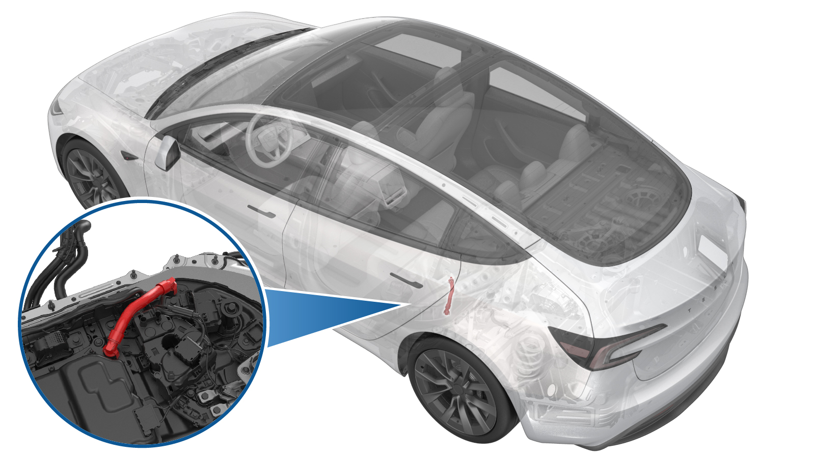
DC Link - Negative - Fast Charge - Ancillary Bay (Remove and Replace)
 Correction code
1630010142
FRT
2.04
NOTE: Unless otherwise explicitly stated in the procedure, the correction code and FRT listed above reflect all of the work required to perform this procedure, including the linked procedures. Do not stack correction codes unless explicitly told to do so.
NOTE: See Flat Rate Times to learn more about FRTs and how they are created.
NOTE: See Personal Protection to make sure you
are wearing proper PPE when performing the procedure below.
NOTE: See Ergonomic Precautions for safe and healthy working practices.
Correction code
1630010142
FRT
2.04
NOTE: Unless otherwise explicitly stated in the procedure, the correction code and FRT listed above reflect all of the work required to perform this procedure, including the linked procedures. Do not stack correction codes unless explicitly told to do so.
NOTE: See Flat Rate Times to learn more about FRTs and how they are created.
NOTE: See Personal Protection to make sure you
are wearing proper PPE when performing the procedure below.
NOTE: See Ergonomic Precautions for safe and healthy working practices.
Equipment:
- 1135762-00-A Kit, Svc Plug, Cooling Hose, Model 3
Only
technicians who have completed all required certification courses are permitted to
perform this procedure. Tesla recommends third party service provider technicians
undergo equivalent training before performing this procedure. For more information on
Tesla Technician requirements, or descriptions of the subject matter for third parties,
see HV Certification Requirements. Proper personal protective equipment (PPE) and insulating HV
gloves with a minimum rating of class 0 (1000V) must
be worn at all times a high voltage cable, busbar, or fitting is handled. Refer to Tech Note TN-15-92-003, High Voltage Awareness
Care Points
for additional safety
information.
Remove
- Move the vehicle to a 2 post lift. See Raise Vehicle - 2 Post Lift.
- Remove the rear underhood apron. See Underhood Apron - Rear (Remove and Replace).
- Disconnect the LV power. See LV Power (Disconnect and Connect).
- Remove the rear aero shield panel. See Panel - Aero Shield - Rear (Remove and Replace).
- Remove the rear HV battery skid plate. See Skid Plate - HV Battery - Rear (Remove and Replace).
- Drain the coolant from the power conversion system. See Ancillary Bay Coolant (Drain and Refill) (Test/Adjust).
- Disconnect the coolant drain hose adapters from the power conversion system inlet and outlet hoses and plug the power conversion inlet and outlet hoses.
- Remove the coolant collection tools, and then remove the coolant pressure tester from underneath the vehicle.
- Lower the vehicle fully.
- Remove the 2nd row lower seat cushion. See Seat Cushion - 2nd Row (Remove and Replace).
- Perform the Vehicle HV Disablement Procedure. See Vehicle HV Disablement Procedure (Test/Adjust).
-
Remove the ancillary bay cover.
See Ancillary Bay Cover (Remove and Replace).
WarningHV insulating gloves and leather glove protectors must be worn throughout the remainder of this procedure. Do not remove gloves or protectors until otherwise noted.
- Remove the pyrotechnic battery disconnect. See Pyro Disconnect - HV Battery (Remove and Replace).
- Remove the HV battery negative contactor. See Pack Contactor - High Voltage - Negative (Remove and Replace).
- Remove the LH ancillary bay terminal cover. See Cover - Left Terminals - Ancillary Bay (Remove and Replace).
- Cut a slit halfway through 2 absorbent pads and surround each coolant output tube fitting with a pad.
-
Use the coolant connector
removal tool to spread the tube fitting clips wider than the barb on the
power conversion system.
- Pull up on the tool and the tube fitting together to disconnect the fitting from the power conversion system.
- Repeat step 17 and step 18 for the other tube fitting at the battery flange.
-
Remove the tube from the
vehicle.
- Install plugs into the power conversion system and the battery flange.
-
Wipe up any spilled
coolant.
CAUTIONSpilled coolant can create an electrical path.
Install
-
Wipe up any spilled coolant.
CAUTIONSpilled coolant can create an electrical path.
-
Make sure that the o-rings are not damaged and that they are properly
seated in the connector groove prior to inserting the tube into the power
conversion system. Replace components as necessary.
WarningThe video(s) included in this procedure are meant as an overview for supplemental purposes only. Follow all of the steps listed in the procedure to avoid damage to components and/or personal injury.
Figure 1. O-rings in good condition - Lubricate the coolant output tube o-rings with Krytox 203 lubricant.
- Remove the plugs from the power conversion system and the battery flange.
- Install the coolant output tube into the power conversion system and the battery flange.
-
Firmly press down on the
tube fittings, to make sure that the fittings are securely connected.
CAUTIONVerify that both clips have fully engaged the barb on the power conversion system and battery flange, and then pull up on the fittings to check retention.
-
Remove the absorbent pads
from around the coolant output tube fittings, and wipe up any spilled
coolant.
CAUTIONSpilled coolant can create an electrical path.
- Install the LH ancillary bay terminal cover. See Cover - Left Terminals - Ancillary Bay (Remove and Replace).
- Install the HV battery negative contactor. See Pack Contactor - High Voltage - Negative (Remove and Replace).
- Install the pyrotechnic battery disconnect. See Pyro Disconnect - HV Battery (Remove and Replace).
- Install the ancillary bay cover. See Ancillary Bay Cover (Remove and Replace).
- Raise the vehicle to a comfortable working height.
- Connect the coolant drain hose adapters to the power conversion system inlet and outlet hoses, and then put the coolant container underneath the vehicle.
- Perform an ancillary bay coolant leak test. See Ancillary Bay Coolant Leak Test (Inspection).
- Install the rear HV battery skid plate. See Skid Plate - HV Battery - Rear (Remove and Replace).
- Install the rear aero shield panel. See Panel - Aero Shield - Rear (Remove and Replace).
- Lower the vehicle fully.
- Refill the coolant. See Ancillary Bay Coolant (Drain and Refill) (Test/Adjust).
- Perform ancillary bay air leak test. See Ancillary Bay Air Leak Test (Inspection).
- Install the 2nd row lower seat cushion. See Seat Cushion - 2nd Row (Remove and Replace).
- Connect the LV power. See LV Power (Disconnect and Connect).
- Remove the rear underhood apron. See Underhood Apron - Rear (Remove and Replace).
- Exit Service mode. See Service Mode.
- Remove the vehicle from the lift. See Raise Vehicle - 2 Post Lift.