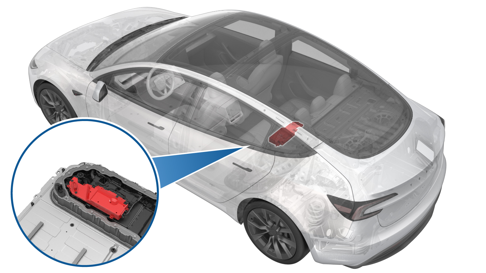
High Voltage Controller (Remove and Replace)
 Correction code
16301602
FRT
1.02
NOTE: Unless otherwise explicitly stated in the procedure, the above correction code and FRT reflect all of the work required to perform this procedure, including the linked procedures. Do not stack correction codes unless explicitly told to do so.
NOTE: See Flat Rate Times to learn more about FRTs and how they are created. To provide feedback on FRT values, email ServiceManualFeedback@tesla.com.
NOTE: See Personal Protection to make sure wearing proper PPE when performing the below procedure.
NOTE: See Ergonomic Precautions for safe and healthy working practices.
-
- 2025-11-14: Added step to apply dielectric grease to the X484 connector. Added step to tuck the pyrotechnic disconnect harness underneath the ancillary bay harness.
- 1453448-01-A Kit Digital Multimeter Set EXTECH 335
- 1076928-00-A Test Probes - Hioki 9461
- 1773092-00-A Diagnostic Harness Adapter - All Models
- 1076928-00-A Hioki tester
- 044097-00-A Dielectric grease or NYE Rheotemp 768G Grease
Only
technicians who have completed all required certification courses are permitted to
perform this procedure. Tesla recommends third party service provider technicians
undergo equivalent training before performing this procedure. For more information on
Tesla Technician requirements, or descriptions of the subject matter for third parties,
see HV Certification Requirements. Proper personal protective equipment (PPE) and insulating HV
gloves with a minimum rating of class 0 (1000V) must
be worn at all times a high voltage cable, busbar, or fitting is handled. Refer to Tech Note TN-15-92-003, High Voltage Awareness
Care Points
for additional safety
information.
| Description | Torque Value | Recommended Tools | Reuse/Replace | Notes |
|---|---|---|---|---|
| Bolts that attach the high voltage controller to the hinge tray |
 2 Nm (1.5 lbs-ft) |
|
Reuse |
Remove
- If the high voltage controller is being removed as part of another component's replacement procedure, and the same controller will be installed later, go to step 3. Otherwise, continue to the next step.
- Perform a backup of the high voltage controller data. See Controller - High Voltage (Backup and Restore).
- Perform Vehicle HV Disablement Procedure. See Vehicle HV Disablement Procedure (Test/Adjust).
-
Remove the ancillary bay cover.
See Ancillary Bay Cover (Remove and Replace).
WarningHV insulating gloves and leather glove protectors must be worn throughout the remainder of this procedure. Do not remove gloves or protectors until otherwise noted.
- Remove the pyrotechnic battery disconnect. See Pyro Disconnect - HV Battery (Remove and Replace).
-
Disconnect the ancillary bay
harness from the high voltage controller connectors.
-
Remove the bolts that attach
the high voltage controller to the hinge tray, and then remove the
controller from the vehicle.
TIpUse of the following tool(s) is recommended:
- Socket External Torx 1/4in Dr. E6
- Insulated
tools:
- Ratchet/torque wrench
- 2 in extension
Install
-
Install the high voltage
controller into the ancillary bay, and then install the bolts that attach the
high voltage controller to the hinge tray.
 2 Nm (1.5 lbs-ft)WarningElectrical protective gloves must be worn.TIpUse of the following tool(s) is recommended:
- Socket External Torx 1/4in Dr. E6
- Insulated
tools:
- Ratchet/torque wrench
- 2 in extension
-
Apply dielectric grease to the X484 connector cavity.
CAUTIONUse a syringe if possible and do not bend the connector pins.
Figure 1. X484 Connector -
Connect the ancillary bay
harness to the high voltage controller connectors.
WarningThe video(s) included in this procedure are meant as an overview for supplemental purposes only. Follow all of the steps listed in the procedure to avoid damage to components and/or personal injury.NoteWipe off any excess grease after inserting the X484 connector.
-
Install the pyrotechnic battery
disconnect. See Pyro Disconnect - HV Battery (Remove and Replace).
NoteDo not connect the LV battery or install the 2nd row seat cushion at this time.
-
Tuck the pyrotechnic disconnect wiring under the main ancillary bay harness.
-
Connect the LV maintainer
charger.
NoteRelease the positive terminal cover, secure the positive terminal to jump post and the negative terminal to bolt located between brake fluid reservoir and front trunk. Connect the maintainer to power supply. To avoid damaging the vehicle, DO NOT allow the positive cable to make contact with other metal components. Never have a float charger and the LV battery simultaneously connected for any extended period of time.
-
Perform a backup of the high
voltage controller data. See Controller - High Voltage (Backup and Restore).
NoteThe environment type for this vehicle is "prod".
- Install the 2nd row seat cushion. See Seat Cushion - 2nd Row (Remove and Replace).
- Disconnect the LV maintainer, and connect the 12V battery. See LV Power (Disconnect and Connect).
- Move the LH and RH front seats to original position.
- Raise all windows and close all doors.