Header - HV - A/C Compressor - HV Battery (Remove and Replace)
 Correction code
1601010032
FRT
0.72
NOTE: Unless otherwise explicitly stated in the procedure, the correction code and FRT listed above reflect all of the work required to perform this procedure, including the linked procedures. Do not stack correction codes unless explicitly told to do so.
NOTE: See Flat Rate Times to learn more about FRTs and how they are created.
NOTE: See Personal Protection to make sure you
are wearing proper PPE when performing the procedure below.
NOTE: See Ergonomic Precautions for safe and healthy working practices.
Correction code
1601010032
FRT
0.72
NOTE: Unless otherwise explicitly stated in the procedure, the correction code and FRT listed above reflect all of the work required to perform this procedure, including the linked procedures. Do not stack correction codes unless explicitly told to do so.
NOTE: See Flat Rate Times to learn more about FRTs and how they are created.
NOTE: See Personal Protection to make sure you
are wearing proper PPE when performing the procedure below.
NOTE: See Ergonomic Precautions for safe and healthy working practices.
Equipment:
- 1457268-00-A Extractor, PTC Heater HV Header, Model 3
- 1080568-00-A Fluid Catcher
- 1135762-00-A Coolant Hose Plug Kit
- 1059330-00-B Socket External Torx 1/4in Dr. E10 5-Lobe
Only
technicians who have completed all required certification courses are permitted to
perform this procedure. Tesla recommends third party service provider technicians
undergo equivalent training before performing this procedure. For more information on
Tesla Technician requirements, or descriptions of the subject matter for third parties,
see HV Certification Requirements. Proper personal protective equipment (PPE) and insulating HV
gloves with a minimum rating of class 0 (1000V) must
be worn at all times a high voltage cable, busbar, or fitting is handled. Refer to Tech Note TN-15-92-003, High Voltage Awareness
Care Points
for additional safety
information.
Torque Specifications
| Description | Torque Value | Recommended Tools | Reuse/Replace | Notes |
|---|---|---|---|---|
| Bolts (x2) that attach the PTC heater and A/C compressor HV header to the HV battery |
 10 Nm (7.4 lbs-ft) |
|
Reuse |
Remove
- Disconnect the LV power. See LV Battery (Remove and Replace).
- Perform the Vehicle HV Disablement Procedure. See Vehicle HV Disablement Procedure (Test/Adjust).
- Remove the rear HV battery skid plate. See Skid Plate - HV Battery - Rear (Remove and Replace).
- Position a coolant drain container under the RH rear of the HV battery.
-
Release the clip, disconnect
the RH inner HV battery return hose fitting from the RH end of the HV
battery platter enclosure, and quickly plug both the male and female
fittings..
- Remove the coolant drain container from under the RH rear of the HV battery.
-
Release the clip that
attaches the RH inner HV battery return hose to the HV battery.
-
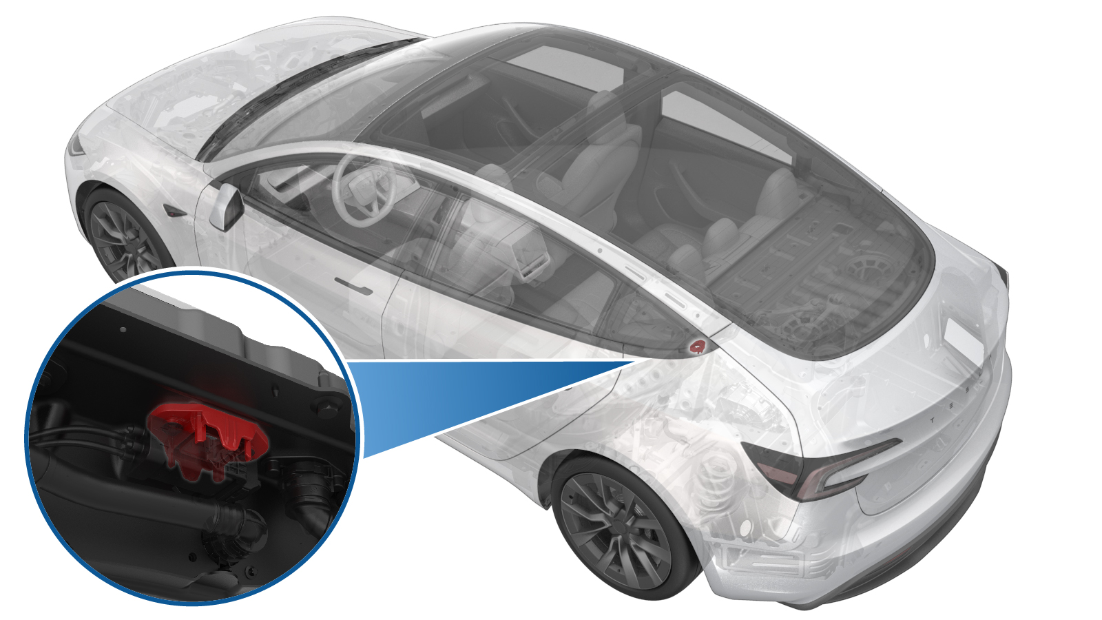
Slide the release to unlock the HV battery PTC heater and A/C compressor connector handle of the PTC heater and A/C compressor to HV battery harness from the secured position.
-
Fully raise the handle on the HV battery PTC heater and A/C compressor connector.
- Remove the HV battery PTC heater and A/C compressor connector from the HV battery header.
-
Remove the bolts (x2) that
attach the PTC heater and A/C compressor HV header to the HV battery.
NoteInspect the 5-lobe bolts shoulder for damage. The bolts are OK to reuse if no damage found.TIpUse of the following tool(s) is recommended:
- External Torx E10 5-Lobe
-
Insert the extractor tool into the PTC heater and A/C compressor HV header, push the tool levers in to release the clips (x2) that attach the header to the PTC heater and A/C compressor pin carrier, and then pull on the header to remove it from the HV battery.
WarningThe video(s) included in this procedure are meant as an overview for supplemental purposes only. Follow all of the steps listed in the procedure to avoid damage to components and/or personal injury.
Install
-
Release the clips (x2) that attach the PTC heater and A/C compressor pin carrier to the bracket inside of the HV battery, and then separate the pin carrier from the bracket.
NotePull down as one clip is released, then release the second clip.WarningThe video(s) included in this procedure are meant as an overview for supplemental purposes only. Follow all of the steps listed in the procedure to avoid damage to components and/or personal injury.
-
Install the PTC heater and A/C compressor pin carrier into the PTC heater and A/C compressor HV header, and fasten the clips (x2) that attach the pin carrier to the header.
NoteUse a plastic pry tool to make sure that the pin carrier fully inserts into the header, and does not move into the HV battery
- Perform a push-pull-push test to make sure the PTC heater and A/C compressor pin carrier is secured in the PTC heater and A/C compressor HV header.
-
Install the PTC heater and A/C compressor HV header onto the HV battery.
NoteMake sure that the PTC heater and A/C compressor pin carrier is secure in the bracket.
-
Install the bolts (x2) that
attach the PTC heater and A/C compressor HV header to the HV battery.10 Nm (7.4 lbs-ft)TIpUse of the following tool(s) is recommended:
- External Torx E10 5-Lobe
- Fully raise the handle on the HV battery PTC heater and A/C compressor connector of the PTC heater and A/C compressor to HV battery harness.
-
Use both hands to firmly connect the HV battery PTC heater and A/C compressor connector of the PTC heater and A/C compressor to HV battery harness to the HV battery header.
CAUTIONMake sure that the connector fits the header squarely and tightly, and that both retention pins enter the handle.
-
While pressing the HV battery PTC heater and A/C compressor connector onto the HV battery header, fully lower the handle.
CAUTIONMake sure that the handle does not bind as it is lowered.
-
Slide the release to lock the HV battery PTC heater and A/C compressor connector handle in the secured position.
-
Verfiy that the HV battery PTC heater and A/C compressor connector is fully seated, and compare both sides of the connector that it is properly secured in place.
NoteAn improperly seated connector might lead to connector damage and PTC heater or A/C compressor problems later on.
-
Install the clip that attaches the RH inner HV battery return hose to the
HV battery.
- Position a coolant drain container under the RH rear of the HV battery.
-
Remove the plugs from the male and female fittings, quickly connect the RH inner HV battery return hose to the HV battery platter enclosure, and then fasten the clip.
- Remove the coolant drain from under the RH rear of the HV battery.
- Install the rear HV battery skid plate. See Skid Plate - HV Battery - Rear (Remove and Replace).
- Perform an ancillary bay air leak test. See Ancillary Bay Air Leak Test (Inspection).
- Connect the LV power. See LV Battery (Remove and Replace).
- Perform a vacuum refill of the cooling system. See Cooling System - Vacuum Refill (Test/Adjust).