2026-07-10
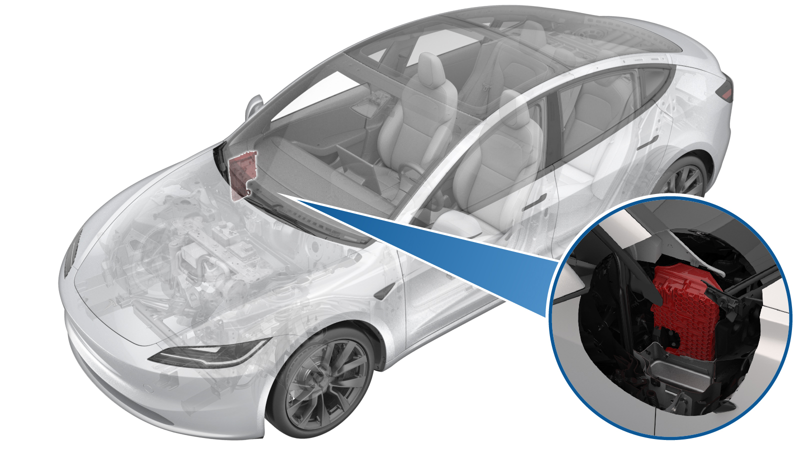
Module - Body Controller - RH (Remove and Replace)
 Correction code
1715010032
FRT
0.78
NOTE: Unless otherwise explicitly stated in the procedure, the correction code and FRT listed above reflect all of the work required to perform this procedure, including the linked procedures. Do not stack correction codes unless explicitly told to do so.
NOTE: See Flat Rate Times to learn more about FRTs and how they are created.
NOTE: See Personal Protection to make sure you
are wearing proper PPE when performing the procedure below.
NOTE: See Ergonomic Precautions for safe and healthy working practices.
Correction code
1715010032
FRT
0.78
NOTE: Unless otherwise explicitly stated in the procedure, the correction code and FRT listed above reflect all of the work required to perform this procedure, including the linked procedures. Do not stack correction codes unless explicitly told to do so.
NOTE: See Flat Rate Times to learn more about FRTs and how they are created.
NOTE: See Personal Protection to make sure you
are wearing proper PPE when performing the procedure below.
NOTE: See Ergonomic Precautions for safe and healthy working practices.
- 2025-03-11: Updated post-replacement routine.
Torque Specifications
| Description | Torque Value | Recommended Tools | Reuse/Replace | Notes |
|---|---|---|---|---|
| Bolt that attaches the LH/RH body controller module to the vehicle |
 4.75 Nm (3.5 lbs-ft) |
|
Reuse |
Remove
- Remove the glove box. See Glove Box (Remove and Replace).
- Remove the RH lower A-pillar trim. See Trim - A-Pillar - Lower - LH (Remove and Replace).
-
Release the lock, and then disconnect the RH front door electrical
connector from the RH body controller module.
-
Release the connector lock, and then disconnect the front passenger seat
electrical connector from the RH body controller module.
-
Disconnect the J10 instrument panel electrical connector from the RH body
controller module.
-
Disconnect the J11 HVAC electrical connector from the RH body controller
module.
-
Release the electrical harness clips
(x2) from underneath the instrument panel carrier.
- Fold back the RH front carpet.
-
Release harness clip from car computer.
-
Disconnect the connector from the
right body harness.
-
Disconnect the connectors (x4) from
the car computer.
-
Release the harness clip
from the RH body controller.
-
Release the connector lock, and then disconnect the J1 power electrical
connector from the RH body controller module.
-
Disconnect the J12 body electrical connector from the RH body controller
module.
-
Release the connector lock, and then disconnect the J4 body electrical
connector from the RH body controller module.
-
Release the connector lock, and then disconnect the J2 body electrical
connector from the RH body controller module.
-
Disconnect the J5 body electrical connector from the RH body controller
module.
-
Disconnect the J6 underhood storage unit electrical connector from the RH
body controller module.
-
Disconnect the connectors (x3) at the
RH lower A-pillar area.
-
Release the RH body harness
from the RH body controller and A-pillar and move aside.
-
Remove the bolt that attaches the RH
body controller module to the body.
TIpUse of the following tool(s) is recommended:
- 10 mm 12-point deep socket
WarningThe video(s) included in this procedure are meant as an overview for supplemental purposes only. Follow all of the steps listed in the procedure to avoid damage to components and/or personal injury. -
Maneuver the RH body controller module
from under the instrument panel, and then remove it from the vehicle.
Install
-
Maneuver the RH body controller module into position under the IP carrier,
and align the W clip with body cut out.
-
Install the bolt that attaches the RH
body controller module to the body.4.75 Nm (3.5 lbs-ft)TIpUse of the following tool(s) is recommended:
- 10 mm 12-point deep socket
-
Secure the clips (x3) that
attach the RH body harness to the RH body controller and A-pillar.
-
Connect the connectors (x3) at the RH lower A-pillar area.
-
Connect the J6 underhood storage unit
electrical connector to the RH body controller module.
-
Connect the J5 body electrical connector to the RH body controller
module.
-
Secure the connector lock, and then connect the J2 body electrical
connector to the RH body controller module.
-
Secure the connector lock, and then connect the J4 body electrical
connector to the RH body controller module.
-
Connect the J12 body electrical connector to the RH body controller
module.
-
Secure the connector lock, and then connect the J1 power electrical
connector to the RH body controller module.
-
Secure harness clip to RH body controller.
-
Connect the connectors (x4) to the car
computer.
-
Connect the connector to the right
body harness.
-
Secure the harness clip to the car
computer.
- Unfold back the RH front carpet.
-
Secure the electrical harness clips
(x2) to underneath the instrument panel carrier.
-
Connect the J11 HVAC electrical connector to the RH body controller
module.
-
Connect the J10 instrument panel electrical connector to the RH body
controller module.
-
Secure the connector lock, and then connect the front passenger seat
electrical connector to the RH body controller module.
-
Secure the lock, and then connect the RH front door electrical connector to
the RH body controller module.
- Install the RH lower A-pillar trim. See Trim - A-Pillar - Lower - LH (Remove and Replace).
- Install the glove box. See Glove Box (Remove and Replace).
- Reinstall the vehicle firmware. See Software Reinstall - Touchscreen.
-
Perform the following
routine using Service Mode or Toolbox (see 0005 - Service Modes):
PROC_CONTROLLER_RIGHT_POST-REPLACEMENT-PROCEDUREvia Service Mode Plus:
- low-voltage ➜ Right Controller Post Replacement ➜ Right Controller Post Replacement Procedure
- mid-voltage ➜ Right Controller Post Replacement ➜ Right Controller Post Replacement Procedure
NoteThe operator needs to sit in the front driver's seat to keep the RH front seat clear from all items/objects during calibration.CAUTIONThe seat will move automatically during this routine. Prior to execution, make sure there is nothing (including objects and aftermarket accessories) behind or underneath the related seat to prevent component damage. - On the touchscreen, press and hold the Exit Service Mode button to exit Service Mode Plus.