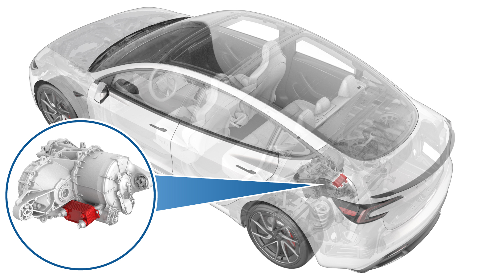
Heat Exchanger - Rear Drive Unit (4DU) (Remove and Replace)
 Correction code
4001010052
FRT
0.72
NOTE: Unless
otherwise explicitly stated in the procedure, the above correction code and
FRT reflect all of the work required to perform this procedure, including
the linked procedures. Do
not stack correction codes unless explicitly told to do so.
NOTE: See Flat Rate
Times to learn more about FRTs and how
they are created. To provide feedback on FRT values, email ServiceManualFeedback@tesla.com.
NOTE: See Personal Protection
to make sure wearing proper PPE when performing the below procedure.
NOTE: See Ergonomic Precautions for safe and
healthy working practices.
Correction code
4001010052
FRT
0.72
NOTE: Unless
otherwise explicitly stated in the procedure, the above correction code and
FRT reflect all of the work required to perform this procedure, including
the linked procedures. Do
not stack correction codes unless explicitly told to do so.
NOTE: See Flat Rate
Times to learn more about FRTs and how
they are created. To provide feedback on FRT values, email ServiceManualFeedback@tesla.com.
NOTE: See Personal Protection
to make sure wearing proper PPE when performing the below procedure.
NOTE: See Ergonomic Precautions for safe and
healthy working practices.
- 1134264-00-A - Drive Unit Oil Drain Kit
- 1541474-00-B - Oil Catch/Measure Kit
Torque Specifications
| Description | Torque Value | Recommended Tools | Reuse/Replace | Notes |
|---|---|---|---|---|
| 4DU oil fill plug |
 15 Nm (11.1 lbs-ft) |
|
Reuse | |
| 4DU oil drain plug |
15 Nm (11.1 lbs-ft) |
|
Reuse | |
| Bolts (x2) that attach the heat exchanger to the drive unit |
5 Nm (3.7 lbs-ft) + 30 degrees |
|
Reuse |
Remove
-
Place the vehicle on the 2-post
lift.
TIpEnsure the vehicle is not charging.
- Open the LH front door and lower the LH front window.
- Remove the rear underhood apron. See Underhood Apron - Rear (Remove and Replace).
- Place the vehicle in Service Mode by using the touchscreen. See Service Mode.
- Disconnect the LV battery power. See LV Power (Disconnect and Connect).
- Remove the rear aero shield panel. See Panel - Aero Shield - Rear (Remove and Replace).
-
Remove the oil fill plug from the 4DU.
TIpUse of the following tool(s) is recommended:
- Flex head ratchet/flex head torque wrench
- 8 mm socket
- 6 in extension
- ¼ in to 3/8 in adapter
- Ratchet/torque wrench
-
Pull the red tab to disengage the
lock, and then pull it again to release the oil pump connector.
- Position an oil drain container under the rear of vehicle.
-
Release the oil drain plug from 4DU drive unit.
NoteSome fluid will drain out.TIpUse of the following tool(s) is recommended:
- Flex head ratchet/flex head torque wrench
- 8 mm socket
-
Connect the 12V power supply to the oil pump switchbox, and then secure the oil pump
switchbox to the oil pump connector.
-
Run the oil pump power supply for 1 minute and drain the remaining oil from the 4DU
drive unit.
NoteTake precaution because the oil will shoot out at a wide angle. Adjust the position of the oil drain container as needed. Do not run oil pump dry for extended period of time.
- Release the power supply and the oil pump switchbox from the oil pump connector.
-
Secure the oil pump connector.
-
Secure the oil drain plug.15 Nm (11.1 lbs-ft)NoteVerify the O-ring is not damaged. Replace O-ring as needed.TIpUse of the following tool(s) is recommended:
- Flex head ratchet/flex head torque wrench
- 8 mm socket
- Remove the oil drain container from underneath the drive unit.
- Position a coolant drain container under the rear of vehicle.
-
Release the clips (x2) that attach the inverter to oil cooler hose to the heat
exchanger, and plug the ends of fittings as soon as possible to avoid coolant
loss.
-
Release the clips (x2) that attach the PT outlet hose to the heat exchanger, and plug
the ends of fittings as soon as possible to avoid coolant loss.
-
Release the bolts (x2) that attach the heat exchanger to the drive unit, and then
remove the heat exchanger from the rear drive unit assembly.
TIpUse of the following tool(s) is recommended:
- Flex head ratchet/flex head torque wrench
- 4 in extension
- External Torx Plus EP10
- Torque wrench with angle measurement
Install
-
Apply a light coat of KAF1 oil to the O-rings of the heat exchanger, and then wipe
away any residue.
-
Install the rear drive unit heat exchanger onto the rear drive unit, and then install
the bolts (x2) that attach the heat exchanger to the drive unit.5 Nm (3.7 lbs-ft) + 30 degreesTIpUse of the following tool(s) is recommended:
- Flex head ratchet/flex head torque wrench
- 4 in extension
- External Torx Plus EP10
- Torque wrench with angle measurement
-
Remove the plugs on the ends of fittings, then secure the clips (x2) that attach the
PT outlet hose to the heat exchanger.
NotePerform a push-pull-push test to make sure that the hose is fully secured.
-
Remove the plugs on the ends of fittings, then secure the clips (x2) that attach the
inverter to oil cooler hose to the heat exchanger.
- Remove the coolant drain container from underneath the vehicle.
- Position the oil drain container under the rear of vehicle.
-
Set up the fill kit (1541474-00-B) with KAF 1, fill the measuring container to 2500
ml.
CAUTIONOnly use KAF1 fluid for the 4DU drive unit. Do not interchange or mix oil types.NoteThe 4DU drive unit will take 2300 ml of fluid, but add extra oil to the container as it will prevent underfill and additional air being injected.
- Trim both input and output hoses to 26 inches, and then insert the output hose into fill hole until it is fully seated. Then pull the hose back 5mm.
-
Place the measured fluid container in the drain basket, fully submerge the input hose
in the fluid, then prime the pump with the drive unit fluid.
-
Pump the fluid into the drive unit.
NoteFill specification for the 4DU drive unit is 2.3L. Excess gearbox fluid in the fill container is used to allow the oil pump to dispense the full 2.3L without drawing air. Pumping the full 2.5L is not required. Make sure that there is less than 200mL left when completed.
-
Install the oil fill plug to the 4DU drive unit.15 Nm (11.1 lbs-ft)NoteVerify the O-ring is not damaged. Replace the O-ring as needed.TIpUse of the following tool(s) is recommended:
- Flex head ratchet/flex head torque wrench
- 8 mm socket
- 6 in extension
- ¼ in to 3/8 in adapter
- Ratchet/torque wrench
- Spray the area with brake cleaner and wipe residual fluid off with towel.
- Remove the oil drain container from underneath the drive unit.
- Install the rear aero shield panel. See Panel - Aero Shield - Rear (Remove and Replace).
- Connect the LV battery power. See LV Power (Disconnect and Connect).
-
On the touchscreen, tap the Service
Mode "wrench" (at the bottom of the touchscreen UI), and then tap , click Run, and then allow the routine to complete.
NoteIf the coolant loss is greater than 1L, perform vacuum fill instead.Note
- The routine will last for a while after the stop message displays. The coolant pumps are audible.
- The test lasts for approximately 10 mins. Do not start another routine during this time.
- Make sure that the vehicle is not in Drive. Putting the vehicle into Drive will stop this routine.
- The speed in the test varies from 3500-6500 RPM (idle speed = ~1500 RPM) and the actuated valve varies between SERIES and PARALLEL.
- If the speed hovers at 7000 RPM, it indicates the pumps are air locked. Perform the vacuum fill again. Continue to add the coolant and purge until the coolant level reaches between the NOM and MAX Lines on the bottle.
-
Inspect the coolant level, top off as
necessary, and then install the coolant bottle cap.
NoteEnsure that the coolant level is at the "Max" line.
- On the touchscreen, tap the Service Mode "wrench" (at the bottom of the touchscreen UI), and then tap , click Run, and allow the routine to complete.
- Exit Service Mode. See Service Mode.
- Install the rear underhood apron. See Underhood Apron - Rear (Remove and Replace).
- Raise the LH front window and close the LH front door.
- Remove the lift arms from below the vehicle.